


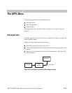

The APPL Menu
3-134 AWG710&AWG710B Arbitrary Waveform Generator User Manual
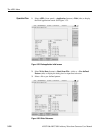
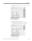
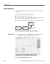
7. If needed, you can repeat adjusting the superpose parameters in this screen and
generate new output waveform.
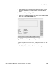
8. Select Superpose (bottom)!Save... (side) to save the generated waveform to
a file.
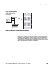
Input data
The specified pattern or waveform file is used as input data. When a pattern data
file is specified for input, the application reads only the MSB bits (DATA7). When
a waveform file is specified, this process converts the values equal to or greater
than 0.5 to a logic 1, and the values less than 0.5 to a logic 0.
The pre–defined patterns shown in Table 3-35 are incorporated in the application:
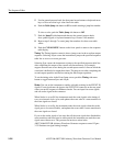
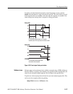
Code Conversion
This part inputs the binary bit pattern and converts the transition from 1 to 0 or 0
to 1 to a series of positive and negative pulse. Table 3-36 lists the available code
conversion types:
NOTE. One restriction is applied to the number of input data points;
input data points > isolated pulse data points / (Samples/Cell)
Table 3-35: Pre–defined patterns
Pattern items Descriptions
X^15 + X + 1 15–bit M–series pseudo random pulse
X^9 + X^5 + 1 9–bit M–series pseudo random pulse
X^7 + X^3 + 1 7–bit M–series pseudo random pulse
32’1’s 32–bit wide data in which all bits are set to 1
Harmonic Elimination Pattern The pattern’s 5th harmonic component is set to 0.
110000001000000110000001000000
Table 3-36: Code Conversion
Code conversion Descriptions
NRZ Converts a transition from 0 to 1 to a positive pulse, and from 1 to 0 to a
negative pulse. This conversion considers the input data as representing a
direction of magnetization.
NRZI Generates a pulse when the input data is 1. The first pulse is always
positive, and after this, the pulse polarity toggles for every input data value
of 1. This conversion considers the input data as representing the disk
writing data.