The Graphical Waveform Editor
3-78 AWG710&AWG710B Arbitrary Waveform Generator User Manual
Digital Filter...
The Digital Filter... command applies a digital filter to the whole of the active
window’s waveform and displays the result in another window. If three windows
are open, the operation will not work.
The digital filter implemented in this instrument is composed of n FIR filter and
Kaizer window functions, where n represents the number of delay elements that
composes the filter. You can specify the n as a tap that varies from 3 to 101. The
larger the value of n (number of taps), the greater the filtering capability. However,
filtering will take a longer time to perform as the value of n increases.
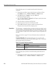
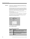
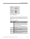
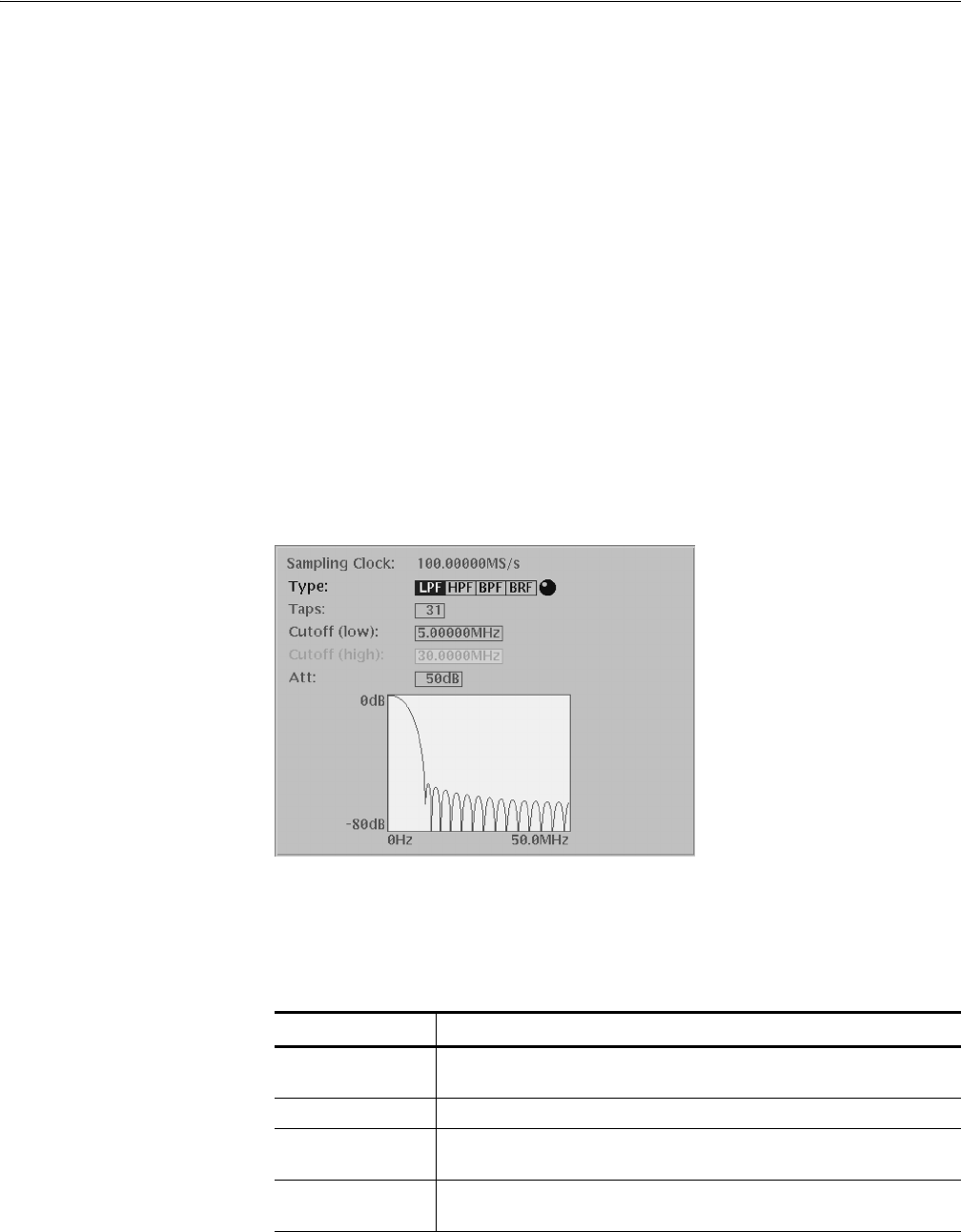
Digital Filter Dialog Box. Figure 3-14 shows the Digital Filter dialog box. Table
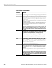
3-17 describes the digital filter parameters.
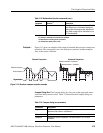
Applying the digital filter results in delay by (number of taps - 1)/2. The original
data is regarded as an iterative waveform during calculation. As a result of the
delay due to the filter, the portion around the start of the output waveform is
influenced by the end of the input waveform.
Figure 3-14: Digital Filter dialog box
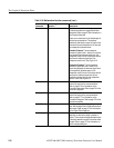
Table 3-17: Digital filter dialog box parameters
Parameters Descriptions
Type Selects the filter type. You can select LPF (low pass filter), HPF (high pass
filter), BPF (band pass filter), or BRF (band rejection filter).
Taps Specifies the number of taps (odd number, 3 to 101).
Cutoff Specifies the cutoff frequency. If you selected BPF or BRF, you must
specify the upper and lower bandpass limits.
Att Specifies the attenuation of the inhibited bands (21 to 100, in dB
increments).


