


Appendix B: Performance Verification (AWG710B)
B-46 AWG710&AWG710B Arbitrary Waveform Generator User Manual
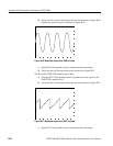
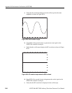
External Clock Input and VCO Out Output Tests
These procedures check the external clock input function and the VCO output
function of the AWG710B Arbitrary Waveform Generator.
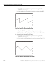
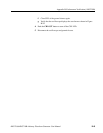
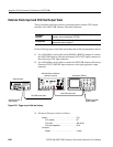
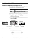
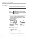
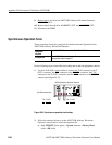
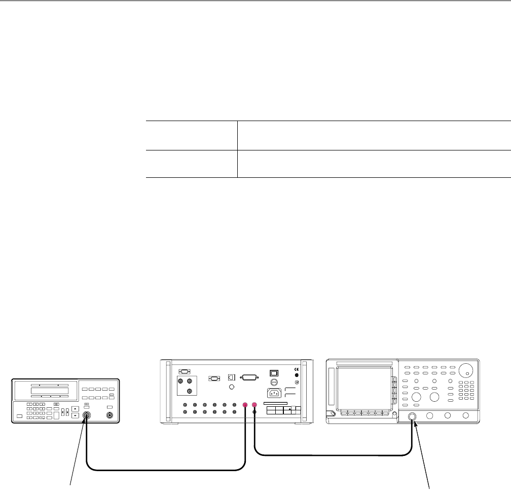
Do the following steps to install the test hookup and set the test equipment controls:
1. Use a 50 Ω SMA coaxial cable and an SMA(Fe)–BNC(Fe) adapter to connect
the AWG710B Arbitrary Waveform Generator VCO OUT output connector to
the oscilloscope CH1 input connector.
2. Use a 50 Ω SMA coaxial cable to connect the AWG710B Arbitrary Waveform
Generator EXT CLOCK IN input connector to the signal generator output
connector.
Figure B-31: Trigger input initial test hookup
3. Set the oscilloscope controls as follows:
Equipment
required
Two 50 Ω SMA coaxial cables, a SMA(Fe)–BNC(Ma) adapter, a signal
generator, and an oscilloscope (TDS700).
Prerequisites
The AWG710B Arbitrary Waveform Generator must meet the
prerequisites listed on page B-7.
Signal Generator
AWG710B Arbitrary Waveform
Generator rear panel
Oscilloscope (TDS700)
50 Ω SMA coaxial cable
VCO OUTOutput
CH1 input
SMA(Female)-BNC
(Male) adapter
SMA(Female)-BNC
(Male) adapter
50 Ω SMA coaxial cable
EXT CLOCK IN
Vertical . . . . . . . . . . . . . . . . . . . . . . . . . . . . . . . . . CH1
CH1 coupling. . . . . . . . . . . . . . . . . . . . . . . . . DC
CH1 scale . . . . . . . . . . . . . . . . . . . . . . . . . . . 200 mV/div
CH1 input impedance . . . . . . . . . . . . . . . . . . 50 Ω
Horizontal
Sweep. . . . . . . . . . . . . . . . . . . . . . . . . . . . . . 2 ns/div