


Appendix B: Performance Verification (AWG710B)
B-34 AWG710&AWG710B Arbitrary Waveform Generator User Manual
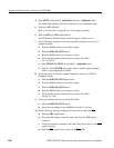
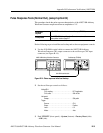
a. Set the function generator controls as follows:
b. Push UTILITY (front–panel)!System (bottom)!Factory Reset
(side)!OK (side).
c. Push SETUP (front–panel)!Run Mode (bottom)!Gated (side).
d. Load the TRIG.WFM file.
Refer to Loading Files on page B-9 for file loading procedures.
4. Push the RUN and CH1 OUT buttons.
The LEDs above the RUN button and CH1 output connector are on.
5. Set the trigger level to 5 V by the following substeps below:
a. Push SETUP (front–panel)!Trigger (bottom)!Level (side).
b. Push 5 and ENTER keys in this order.
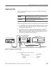
6. Set the trigger input signal level to 4.65 V by the following substeps below:
a. Turn on the function generator output.
b. Select offset by pressing the OFFSET button of function generator.
c. Set the DC waveform high level to 4.65 V by using cursor keys.
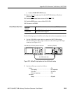
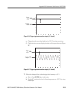
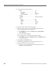
d. Check that no waveform is displayed on the oscilloscope as shown in
Figure B-16.
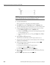
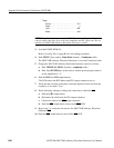
CH1 input impedance . . . . . . . . . . . . . . . . . . 50 Ω
CH2 input impedance . . . . . . . . . . . . . . . . . . 1 M Ω
Horizontal
Sweep. . . . . . . . . . . . . . . . . . . . . . . . . . . . . . 1 ms/div
Trigger
Source. . . . . . . . . . . . . . . . . . . . . . . . . . . . . . CH1
Coupling . . . . . . . . . . . . . . . . . . . . . . . . . . . . DC
Slope. . . . . . . . . . . . . . . . . . . . . . . . . . . . . . . Positive
Level . . . . . . . . . . . . . . . . . . . . . . . . . . . . . . . +100 mV
Mode. . . . . . . . . . . . . . . . . . . . . . . . . . . . . . . Auto
Function . . . . . . . . . . . . . . . . . . . . . . . . . . . . . . . .DC
Mode. . . . . . . . . . . . . . . . . . . . . . . . . . . . . . . . . . .Continuous
Output . . . . . . . . . . . . . . . . . . . . . . . . . . . . . . . . . .Off