


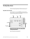
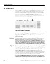
The Setup Menu Screen
AWG710&AWG710B Arbitrary Waveform Generator User Manual 3-41
Clock Out
The instrument also outputs the internal clock signal to the rear panel VCO OUT
(1/4 CLOCK OUT : AWG710) connector. Table 3-5 describes the VCO OUT (1/4
CLOCK OUT : AWG710) signal timing as it relates to the active Run Mode.
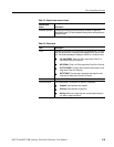
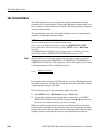
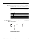
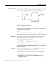
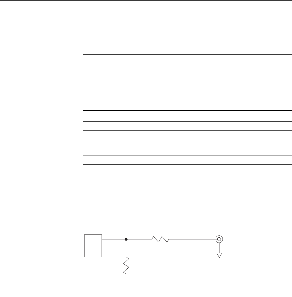
1/4 Clock Out (AWG710
only)
The instrument outputs the internal clock signal to the rear panel 1/4 CLOCK OUT
connector (see Figure 3-3).
Figure 3-3: 1/4 CLOCK OUT output format
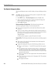
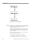
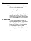
Three connection methods are available. Refer to Figure 3-4.
NOTE. When you push the RUN button, the instrument outputs a pulse signal for a
short period of time on the VCO OUT (1/4 CLOCK OUT : AWG710)connector (not
related to the clock signal). This signal is generated for the instrument internal
setup.
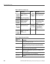
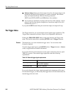
Table 3-5: Clock signal output timing
Run modes Timing
Continuous The clock signal is always output when the RUN LED on the front–panel is on.
Triggered The clock signal is always output when a waveform is being output. When the
instrument waits for a trigger event, no clock output is provided.
Gated The clock signal is always output when the RUN LED on the front–panel is on.
Enhanced The clock signal is always output except the instrument is in the trigger wait state.
MC100EL57
1/4 CLOCK OUT
47 Ω
51 Ω
–2 V