


The Setup Menu Screen
3-42 AWG710&AWG710B Arbitrary Waveform Generator User Manual
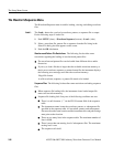
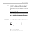
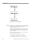
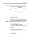
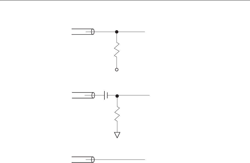
(1) 50Ω terminated to VBB (-1.3V)
(2) 50Ω terminated with AC coupling
(3) Not terminated (High impedance)
Figure 3-4: 1/4 CLOCK OUT connection examples
Clock Ref
This button lets you set the instrument clock source. You can specify the internal
clock generator or an external 10 MHz clock signal connected to the rear panel 10
MHz REF IN connector. The acceptable external clock signal is
10 MHz ± 0.1 MHz, 0.2 V
p–p
to 3.0 V
p–p
.
The instrument synchronizes the internal sample clock phase–lock–loop (PLL)
generator to the external clock. Using an external sample clock can help you
synchronize the AWG710&AWG710B Arbitrary Waveform Generator with the
rest of your test equipment.
If you use the external clock as the reference clock, you can change the output
waveform clock rate like the internal clock.
Use the following procedure to select the reference clock source:
1. Push SETUP (front)!Horizontal (bottom)!Clock Ref (side).
2. Push the Clock Ref side button to toggle between Internal and External.
50 Ω
50 Ω
–1.3 V
50 Ω
50 Ω
50 Ω