


Appendix B: Performance Verification (AWG710B)
B-30 AWG710&AWG710B Arbitrary Waveform Generator User Manual
3. Load the PULSE.WFM file.
Refer to Loading Files on page B-9 for file loading procedures.
4. Push SETUP (front–panel)!Run Mode (bottom)!Continuous (side).
The AWG710B Arbitrary Waveform Generator is set to the Continuous mode.
5. Change the AWG710B Arbitrary Waveform Generator controls as follows:
a. Push VERTICAL MENU (bottom)!Amplitude (side).
b. Push 1 and ENTER keys in this order or turn the general purpose knob to
set the amplitude to 1 V.
6. Push the RUN and CH1 output buttons.
The LEDs above the RUN button and CH1 output connectors are on.
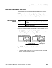
7. Verify that the rise time of the pulse waveform displayed on the oscilloscope
is equal to or less than 175 ps.
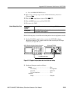
8. Do the following substeps to change the connection to check the CH1
:
a. Push the CH1 output button.
b. Disconnect the cable from the CH1 output connector.
c. Connect the cable to the CH1
output connector.
d. Push the CH1
output button to turn on the CH1 LED.
9. Repeat step 7 to verify the rise time for the AWG710B Arbitrary Waveform
Generator CH1
.
10. Push the CH1
output button to turn off the CH1 LED.
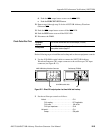
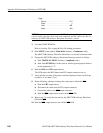
Trigger
Source. . . . . . . . . . . . . . . . . . . . . . . . . . . . . . CH1
Slope. . . . . . . . . . . . . . . . . . . . . . . . . . . . . . .
Level . . . . . . . . . . . . . . . . . . . . . . . . . . . . . . . 0 V
Mode. . . . . . . . . . . . . . . . . . . . . . . . . . . . . . . Auto
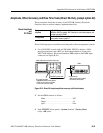
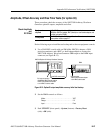
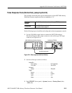
NOTE. The pulse rise time tests use the AWG710B Arbitrary Waveform Generators
control settings that have been used in the amplitude and DC offset tests. Do not
initialize the AWG710B Arbitrary Waveform Generator controls.