


Appendix B: Performance Verification (AWG710)
AWG710&AWG710B Arbitrary Waveform Generator User Manual B-91
Event Input and Enhanced Mode Tests
These procedures check the event input signals and enhanced mode operation.
Check Event Input with
Strobe Off
Do the following steps to install the test hookup and set the test equipment controls:
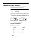
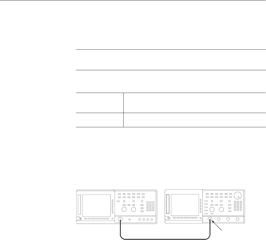
1. Use a 50Ω SMA coaxial cable and a SMA(Fe)–BNC(Fe) adapter to connect
the AWG710 Arbitrary Waveform Generator CH1 output connector to the
oscilloscope CH1 input connector (see Figure B-54).
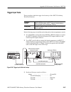
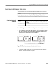
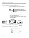
Figure B-54: Event input and enhanced mode initial test hookup
2. Connect the ground closure to the EVENT IN connector on the AWG710
Arbitrary Waveform Generator rear panel.
NOTE. The event input check with strobe off and the strobe input check are
structured as a continuous test. After Check Event Input with Strobe Off, the next
test uses the connections and oscilloscope settings from the previous test.
Equipment
required
A 50 Ω SMA coaxial cable, a SMA(Fe)–BNC(Ma) adapter an oscilloscope
(TDS700), and custom–made ground closure. See Figure B-37 for the
connections.
Prerequisites
The AWG710 Arbitrary Waveform Generator must meet the prerequisites
listed on page B-61.
AWG710 Arbitrary Waveform Generator Oscilloscope (TDS700)
50 Ω SMA coaxial cable
SMA(Female)-BNC
(Male) adapter