


Appendix B: Performance Verification (AWG710B)
AWG710&AWG710B Arbitrary Waveform Generator User Manual B-15
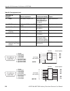
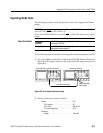
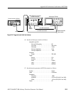
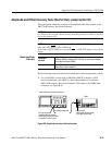
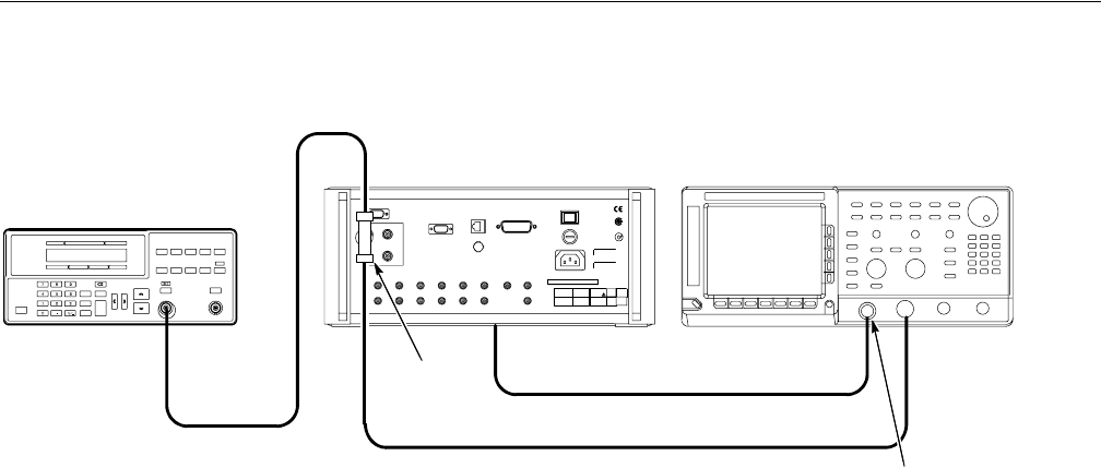
Figure B-6: Triggered mode initial test hookup
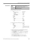
4. Set the oscilloscope controls as follows:
5. Set the function generator (AFG310) controls as follows:
50Ω BNC coaxial cable
Oscilloscope (TDS700)
CH1 input CH2 input
SMA(Female)-BNC
(Male) adapter
BNC-T
Adapter
Function Generator (AFG310)
Output
AWG710B Arbitrary Waveform
Generator rear panel
50 Ω SMA coaxial cable
50 Ω BNC coaxial cable
CH1 output
VerticalCH1 and CH2
CH1 and CH2 coupling . . . . . . . . . . . . . . . . . DC
CH1 scale . . . . . . . . . . . . . . . . . . . . . . . . . . . 500 mV/div
CH2 scale . . . . . . . . . . . . . . . . . . . . . . . . . . . 2 V/div
CH1 input impedance . . . . . . . . . . . . . . . . . . 50 Ω
CH2 input impedance . . . . . . . . . . . . . . . . . . 1 MΩ
Horizontal
Sweep . . . . . . . . . . . . . . . . . . . . . . . . . . . . . . 200 ns/div
Trigger
Source. . . . . . . . . . . . . . . . . . . . . . . . . . . . . . CH1
Coupling . . . . . . . . . . . . . . . . . . . . . . . . . . . . DC
Slope. . . . . . . . . . . . . . . . . . . . . . . . . . . . . . . Positive
Level . . . . . . . . . . . . . . . . . . . . . . . . . . . . . . . +100 mV
Mode . . . . . . . . . . . . . . . . . . . . . . . . . . . . . . . NORMAL
Function . . . . . . . . . . . . . . . . . . . . . . . . . . . . . . . . Square
‘Mode . . . . . . . . . . . . . . . . . . . . . . . . . . . . . . . . . . Continuous
Parameters
Frequency . . . . . . . . . . . . . . . . . . . . . . . . . . . 1 MHz
Amplitude . . . . . . . . . . . . . . . . . . . . . . . . . . . 2.0 V into 50 Ω (4.0 V into 1 MΩ)
Offset. . . . . . . . . . . . . . . . . . . . . . . . . . . . . . . 1.0 V into 50 Ω (2.0 V into 1 MΩ)
Output . . . . . . . . . . . . . . . . . . . . . . . . . . . . . . . . . . Off