


Appendix B: Performance Verification (AWG710B)
B-18 AWG710&AWG710B Arbitrary Waveform Generator User Manual
e. Push 1, 0, 0 and M (SHIFT+7) keys in this order or turn the general
purpose knob to set the internal clock frequency to 100 MHz.
f. Push the RUN and CH1 output buttons.
The LEDs above the RUN button and CH1 output connector are on.
g. Push the FORCE TRIGGER button.
Verify that the oscilloscope displays sine waves while the FORCE TRIGGER
button is pushed and that the output stops when the Force Trigger button is
released.
4. Follow the substeps below to check the gated mode with the gate signal:
a. Set the oscilloscope trigger source to CH2 and change the trigger level to
1 V.
b. Turn on the function generator output.
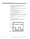
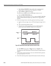
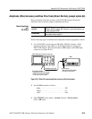
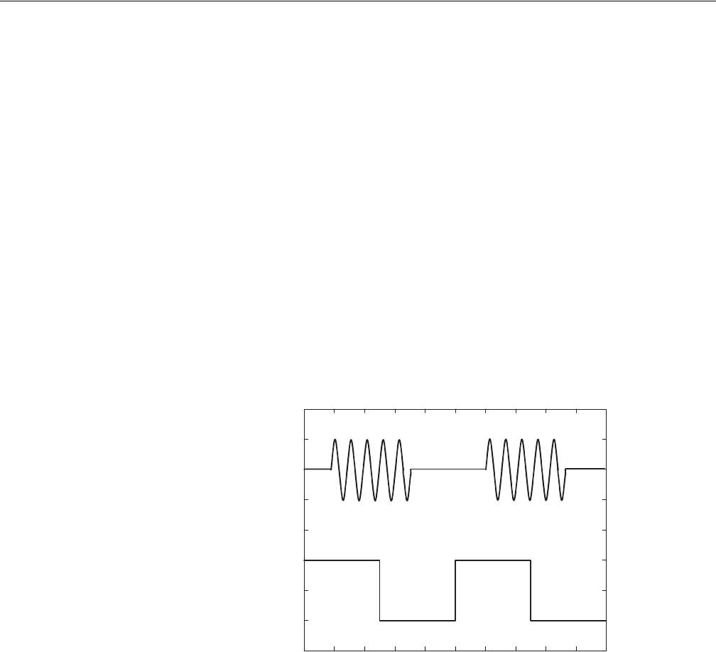
c. Verify that the oscilloscope displays sine waves while the function
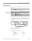
generator gate signal amplitude is High level. See Figure B-8.
Figure B-8: Relationship between gate signal and waveform output
d. Push SETUP (front–panel)!Trigger (bottom)!Negative (side).
This changes the AWG710B Arbitrary Waveform Generator trigger polarity to
negative.
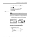
5. Verify that the oscilloscope displays sine waves while the function generator
gate signal amplitude is Low level.
6. Turn off the function generator output and disconnect from the oscilloscope.
Waveform
output
Gate
signal
CH1
CH2