


FG Mode
AWG710&AWG710B Arbitrary Waveform Generator User Manual 3-239
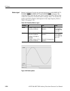
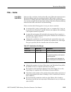
Frequency and Resolution
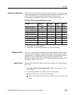
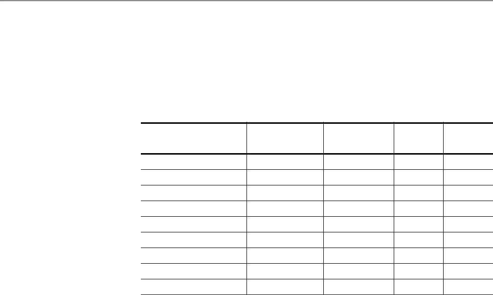
While operating in FG mode, the output frequency determines the number of data
points used to generate the waveform data and the marker data for one period. The
resolution of Pulse Duty cycle ratio and the width of Marker position
corresponding to the number of data points are shown in the following table.
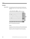
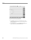
Save/Restore Setup
You can save and restore the instrument output setup information on FG mode to
a setup file. Setup file includes waveform type, marker signals and all the output
setup parameters. Save/Restore operation is executed on the Save/Restore menu of
the SETUP screen in AWG mode. A saved setup file contains the setting
information on both AWG mode and each Extended Operation mode. Refer to The
Save/Restore Menu on page 3-48.
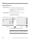
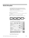
Operation Flow
When the AWG710&AWG710B is in AWG mode, change to FG mode. Reference
page 3-234.
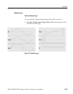
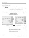
1. Push Sine, Triangle, Square, Ramp, Pulse or DC (bottom) button to select
the waveform.
2. Set the output parameters according to the waveform selected.
Duty is added to the side menu for Pulse mode.
Offset is only used for setup of DC level. Offset is selected on the DC side
menu.
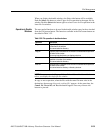
Table 3-56: Output Frequency and Waveform Length
Frequency Number of
Data Points
Duty Ratio
Resolution (%)
Marker1
position
1
Marker2
position
2
1.000Hz to 400.0kHz 10000 0.1 2000 5000
400.1kHz to 4.000MHz 1000 0.1 200 500
4.001MHz to 20.00MHz 200 0.5 40 100
20.01MHz to 40.00MHz 100 1 20 50
40.01MHz to 80.0MHz 50 2 10 25
80.01MHz to 100.0MHz 40 2.5 8 20
100.1MHz to 160.0MHz 25 4 5 13
3
160.01MHz to 200.0MHz 20 5 4 10
200.01MHz to 400.0MHz 10 10 2 5
1: 20% position of 1 waveform period
2: 50% position of 1 waveform period
3: 52% position of 1 waveform period because of number of data points.