


Operating Basics
2-42 AWG710&AWG710B Arbitrary Waveform Generator User Manual
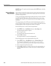
Extended operation. Selecting a Extended operation from the Extended Operation
menu causes one of the following to operate the AWG710&AWG710B Arbitrary
Waveform Generator:
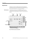
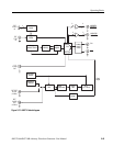
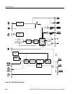
Analog Circuit. The Analog Circuit block contains the Filter, Attenuator, Output
Amplifier, Calibration and Offset Circuits. These circuits are used to process
signals generated from the DAC. Option02 has Calibration Circuits only.
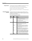
Gated The waveform is output only while:
An external trigger signal from the rear panel’s TRIG IN connector.
A gate signal through the front–panel’s FORCE TRIGGER button is TRUE.
A control command such as trigger or event from remote device. (Except
the Synchronous operation mode)
Enhanced The waveform is obtained, in the order defined with the sequence, based on:
A trigger signal (for example, an external trigger signal from the rear panel’s
TRIG IN connector).
An event signal from the rear panel’s EVENT IN connector.
An trigger signal from the front panel’s FORCE TRIGGER button.
An event signal from the front panel’s FORCE EVENT button.
A control command such as trigger, event or jump from remote device.
(Except the Synchronous operation mode)
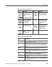
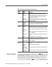
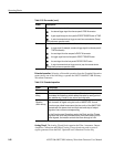
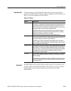
Table 2-14: Extended operation
Modes Descriptions
FG Enter the FG mode for easy generate of a standard functional waveform.
Waveform
Mixing
Create and output a mixed waveform. Waveform mixing
generates the waveform which added the value for every point of
two waveforms, A and B, at a rate of a mixing ratio.
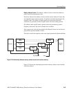
Synchronous
Operation
(AWG710B only)
Synchronous Operation is a feature that outputs synchronized
two channels of signal using two units of AWG710B. A word
synchronous called here means that two units of the AWG710B
operate with the same clock and that start and stop of output
signals of two units are corresponding.
In the Synchronous Operation mode, the Clock and the Trigger
signals of two units are provided directly from the master unit. For
other signals, the master controls the slave through a LAN.
Table 2-13: Run modes (cont.)
Modes Descriptions