Appendix A: Specifications (AWG710B)
A-18 AWG710&AWG710B Arbitrary Waveform Generator User Manual
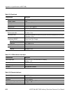
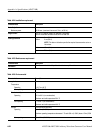
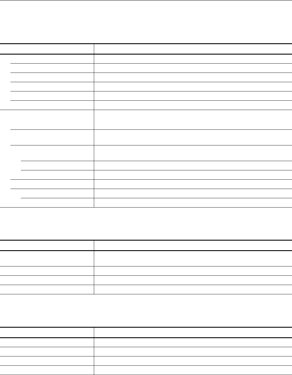
Table A-14: Event Input
Characteristics Description
Connector 9–pin, D type on the rear panel
Number of events 7 bits
Input signal 7 event bits and Strobe
Threshold TTL level
Maximum input 0 V to + 5 V (DC + peak AC)
Impedance 1 kΩ, pull–up to +3.3 V
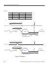
Enhanced mode
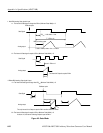
Minimum pulse width 320 clocks + 10 ns
Event hold off time (The time interval between the last event input point and the next acceptable event input point)
≤ 896 clocks + 20 ns
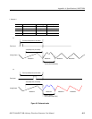
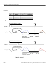
Delay to analog out, Typical
(Jump timing: ASYNC) (Output: Norm, Filter: Through)
Strobe: On 1691.5 clocks + 10 ns
Strobe: Off 1947.5 clocks + 6 ns
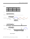
Event input to strobe input
Setup time 192 clocks + 10 ns
Hold time 192 clocks + 10 ns
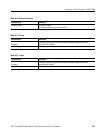
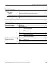
Table A-15: 10 MHz reference clock input
Characteristics Description
Input voltage range 0.2 V
p–p
to 3.0 V
p–p
(into a 50 Ω load, AC coupling)
Maximum ±10 V
Impedance 50 Ω, AC coupling
Frequency range 10 MHz ±0.1 MHz
Connector Rear panel BNC connector
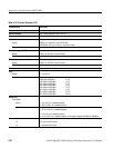
Table A-16: External clock input
Characteristics Description
Connector Rear panel SMA connector
Impedance 50 Ω, AC coupling
Required input voltage range swing 0.4 V
p–p
to 2 V
p-p
into a 50 Ω load
Required duty cycle 50 ±5 %


