


Appendix A: Specifications (AWG710B)
A-8 AWG710&AWG710B Arbitrary Waveform Generator User Manual
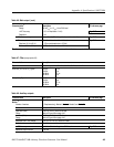
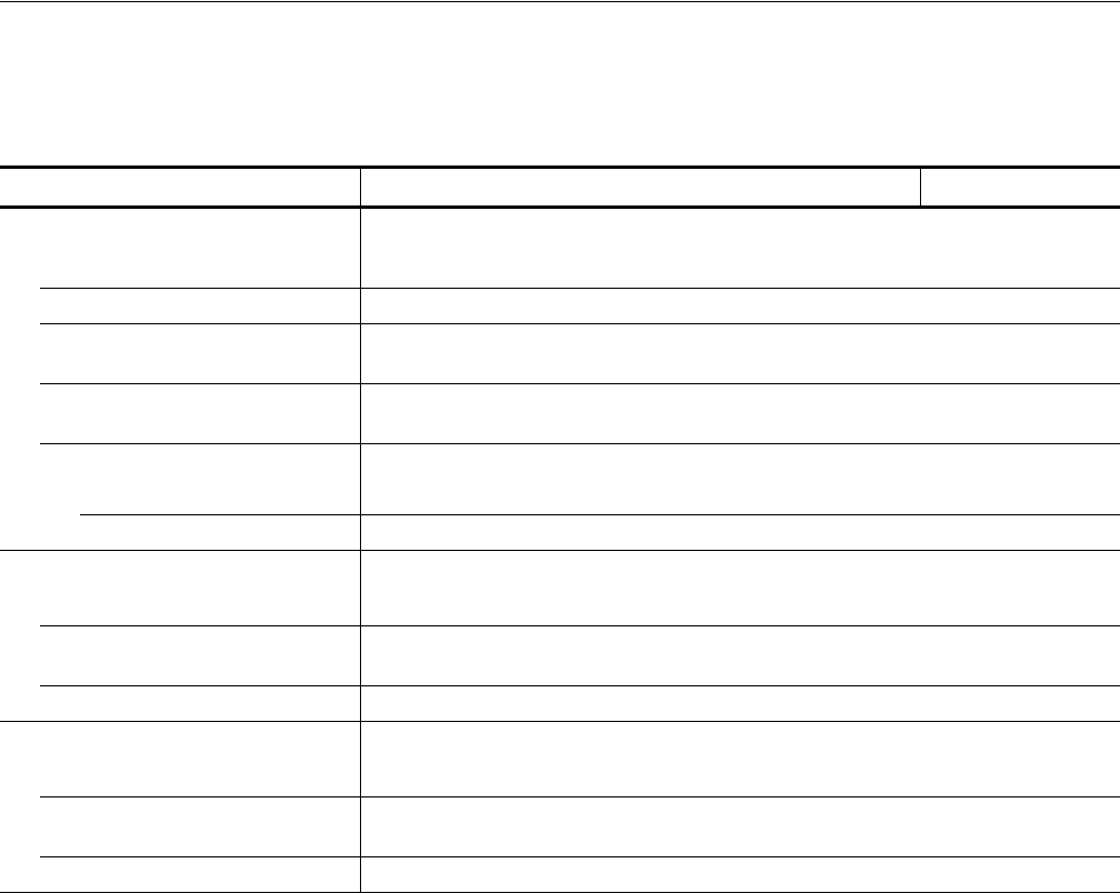
Table A-13: Auxiliary inputs
Characteristics Description PV reference page
Trigger input
5
Connector Rear panel BNC connector
Impedance 1 kΩ or 50 Ω
Polarity (Trigger mode)/
Slope (Gated mode)
POS (positive) or NEG (negative)
Input voltage range ±10 V, into a 1 kΩ load
±5 V, into a 50 Ω load
Threshold
Level -5.0 V to 5.0 V
Resolution 0.1 V
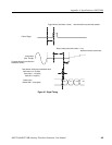
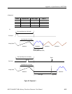
Triggered mode
See Figure A-1 on page A-9
Minimum pulse width 10 ns, 0.2 V amplitude
Trigger hold off time ≤ 109.5 clocks + 500 ns ; Single operation
≤ 109.5 clocks + 700 ns ; Synchronous operation
Delay to analog out, Typical 275.5clocks + 17 ns (Output: Norm, Filter: Through)
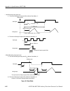
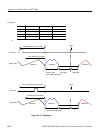
Gated mode See Figure A-2 on page A-10
Minimum pulse width 1152 clocks + 10 ns, 0.2 V amplitude
Gate hold off time ≤ 1920 clock + 20 ns (The time interval between the last gate off point and the next gaate on
point)
Delay to analog out, Typical (1355 to 1563.5) clocks + 9 ns (Output: Norm, Filter: Through)
5
The characteristics are specified at the end of the BNC cable (012–0482–00).