


The Graphical Waveform Editor
AWG710&AWG710B Arbitrary Waveform Generator User Manual 3-67
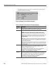
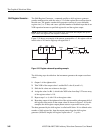
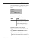
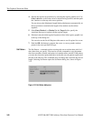
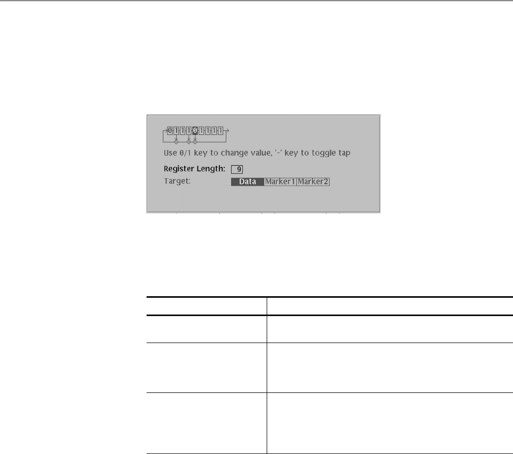
The Shift Register Generator dialog box lets you define the register length, initial
register bit values, and XOR tap bits used to generate pseudo–random pulses.
Figure 3-11 shows the dialog box, and Table 3-11 describes the dialog box
parameters.
Figure 3-11: Shift Register Generator dialog box
Do the following steps to generate a set of pseudo–random pulses:
1. Move the cursors to specify the edit area to replace with the pseudo–random
signal.
2. Push Operation (bottom)!Shift Register Generator... (pop–up)!OK
(side).
The Shift Register Generator dialog box appears.
3. Specify a register length in the Register Length field.
The graphical register icon at the top of the dialog box redraws to show the
number of registers entered in the Register Length field. The value can be 0 to
32.
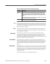
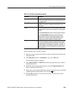
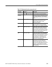
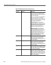
Table 3-11: Shift Register Generator dialog box setting parameters
Parameter Description
Register Icon The Register Icon displays the current register length and tap
position values at the top left side of the dialog box.
Register Length Specifies the register length. Set a value from 1 to 32 using the
general purpose knob or numeric buttons. The graphic register
image in the dialog box will change to show the number of
registers you enter.
Target Specifies the location where the generated pseudo–random pulse
data is created. Selecting Data replaces the waveform data.
Selecting Marker1 or Marker2 replaces the marker data. If the
register data has fewer data points than those in the edit area, the
register output repeats until the end of the edit area.