


Appendix B: Performance Verification (AWG710B)
AWG710&AWG710B Arbitrary Waveform Generator User Manual B-29
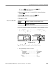
e. Push the FORCE EVENT button.
11. Repeat steps 7 through step 9 for the AWG710B Arbitrary Waveform
Generator CH1
.
12. Push the CH1
output button to turn off the CH1 LED.
13. Push the RUN button to turn off the RUN LED.
14. Disconnect the DMM.
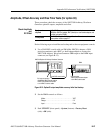
Check Pulse Rise Time
Do the following steps to install the test hookup and set the test equipment controls:
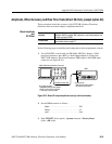
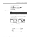
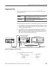
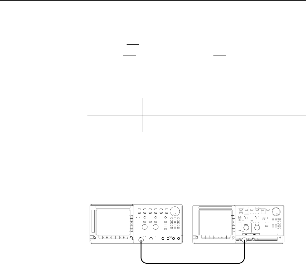
1. Use the 50 Ω SMA coaxial cable to connect the AWG710B Arbitrary
Waveform Generator CH1 output connector to the oscilloscope CH1 input
connector (see Figure B-13).
Figure B-13: Optipn02 output pulse rise time initial test hookup
2. Set the oscilloscope controls as follows:
Equipment
required
A 50 Ω SMA coaxial cable and an oscilloscope (TDS820).
Prerequisites
The AWG710B Arbitrary Waveform Generator must meet the
prerequisites listed on page B-7.
Vertical . . . . . . . . . . . . . . . . . . . . . . . . . . . . . . . . . CH1
CH1 coupling. . . . . . . . . . . . . . . . . . . . . . . . . DC if applicable
CH1 scale . . . . . . . . . . . . . . . . . . . . . . . . . . . 200 mV/div
CH1 input impedance . . . . . . . . . . . . . . . . . . 50 Ω
Horizontal
Sweep . . . . . . . . . . . . . . . . . . . . . . . . . . . . . . 200 ps/div
AWG710B option 02 Arbitrary Waveform Generator Oscilloscope (TDS820)
50 Ω SMA coaxial cable