


Programming Examples
3-212 AWG710&AWG710B Arbitrary Waveform Generator User Manual
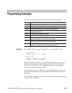
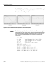
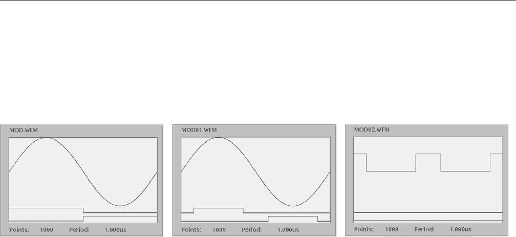
The MOD02.WFM signal is 0.5 if the marker1 signal of the MOD01.WFM is equal
to the marker2 signal, otherwise the signal value is 0.
The results are shown in Figure 3-67.
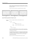
Figure 3-67: Source waveform and those generated by the Example 4 equation
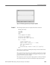
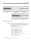
Example 5
The following example shows how to use filter functions. There are four digital
filter functions: lpf(), hpf(), bpf() and brf(), which are the same as those provided
in the digital filter dialog box of the waveform editor. Refer to Digital Filter... on
page 3-78 for more information on the filter arguments and the digital filter
characteristics.
size = 2000
hf = 45e6 ' Cutoff frequency High: 1 Hz to 50 MHz
lf = 5e6 ' Cutoff frequency Low
: 1 Hz to 50 MHz
taps = 97 ' Taps: 3 to 101
att = 30 ' Attenuation: 21 dB to 100 dB
"NOISE.WFM" = noise()
"NOISE.WFM" = norm("NOISE.WFM")
"N1.WFM" = lpf("NOISE.WFM", lf, taps, att)
"N2.WFM" = hpf("NOISE.WFM", hf, taps, att)
"N3.WFM" = bpf("NOISE.WFM", lf, hf, taps, att)
"N4.WFM" = brf("NOISE.WFM", lf, hf, taps, att)
MOD.WFM MOD01.WFM MOD02.WFM