


Appendix B: Performance Verification (AWG710B)
AWG710&AWG710B Arbitrary Waveform Generator User Manual B-43
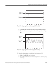
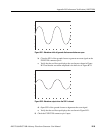
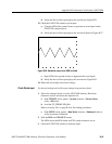
d. Verify that the oscilloscope displays the waveform in Figure B-21.
13. Check the EVENT IN connector pin 6 input:
a. Close the SW8of the ground closure to generate an event signal on the
EVENT IN connector pin 6.
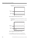
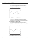
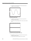
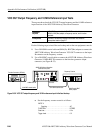
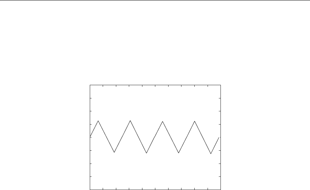
b. Verify that the oscilloscope displays the waveform shown in Figure B-27.
Figure B-28: Waveform output when SW8 is closed
c. Open SW8 of the ground closure to degenerate the event signal.
d. Verify that the oscilloscope displays the waveform in Figure B-21.
14. Retain the test hookup and control settings.
Check Strobe Input
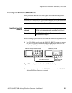
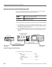
Use the test hookup and oscilloscope settings from previous check.
1. Follow the substeps below to set the AWG710B Arbitrary Waveform
Generator controls and select the sequence file:
a. Push UTILITY (front–panel)!System (bottom)!Factory Reset
(side)!OK (side).
b. Load the PT_STROB7.SEQ file.
Refer to Loading Files on page B-9 for file loading procedures.
c. Push SETUP (front–panel)!Run Mode (bottom)!Enhanced (side) to
set the run mode to enhanced.
2. Push the RUN and CH1 OUT buttons.
The LEDs above the RUN button and CH1 output connector are on.
3. Check the EVENT IN connector strobe pin input: