


Appendix B: Performance Verification (AWG710B)
B-50 AWG710&AWG710B Arbitrary Waveform Generator User Manual
Marker Output Tests
These procedures check the accuracy of the AWG710B Arbitrary Waveform
Generator marker output level.
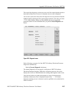
Do the following steps to install the test hookup and set the test equipment controls:
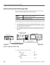
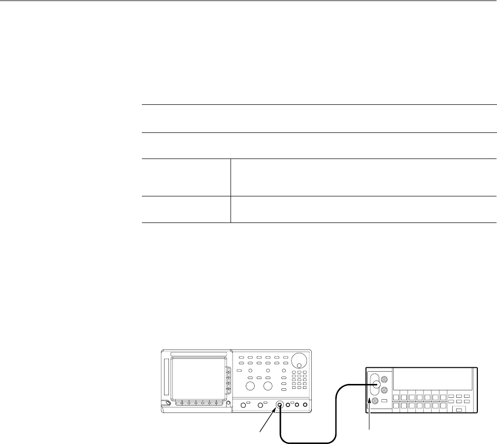
1. Use a 50 Ω BNC coaxial cable, a SMA(Ma)–BNC(Fe) adapter, a 50 Ω
precision terminator, and a BNC–to–dual banana adapter to connect the
AWG710B Arbitrary Waveform Generator MARKER 1 OUT to the DMM
input connector (see Figure B-33).
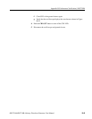
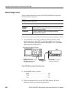
Figure B-33: Marker output initial test hookup
2. Set the DMM controls as follows:
3. Follow the substeps below to set the AWG710B Arbitrary Waveform
Generator controls and to select the sequence file:
NOTE. Connect a 50
Ω
SMA terminator to the inverted marker output connector
during the marker output tests.
Equipment
required
A 50 Ω BNC coaxial cable, a 50 Ω precision terminator, a
SMA(Ma)–BNC(Fe) adapters, BNC (female)–to–dual banana adapter,
and a digital multimeter (DMM).
Prerequisites
The AWG710B Arbitrary Waveform Generator must meet the
prerequisites listed on page B-7.
Mode. . . . . . . . . . . . . . . . . . . . . . . . . . . . . . . . . . . VDC
Range . . . . . . . . . . . . . . . . . . . . . . . . . . . . . . . . . . Auto
Input . . . . . . . . . . . . . . . . . . . . . . . . . . . . . . . . . . . Front
AWG710B Arbitrary Waveform Generator
DMM
50Ω BNC coaxial
cable
MARKER 1 out connector
+ SMA(Male)-BNC(Female) adapter
+ BNC 50Ω precision terminator
+ 50 Ω BNC coaxial cable
Input connector
+ BNC-to-dual banana adapter
+ 50 Ω BNC coaxial cable