


Appendix A: Specifications (AWG710)
AWG710&AWG710B Arbitrary Waveform Generator User Manual A-31
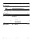
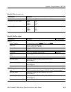
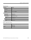
Table A-35: Filter
(except option 02)
Characteristics Description
Type Bessel low pass filter, 200 MHz,100 MHz, 50 MHz, and 20 MHz
Rise time (10 % to 90 %), Typical 20 MHz
50 MHz
100 MHz
200 MHz
17 ns
7 ns
3.7 ns
2 ns
Group delay, Typical 20 MHz
50 MHz
100 MHz
200 MHz
18 ns
8 ns
4.7 ns
3 ns
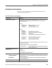
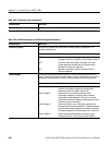
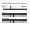
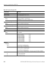
Table A-36: Auxiliary outputs
Characteristics Description PV reference page
Marker
4
Number of markers 2 ( Complementary). Marker1, Marker1, Marker2, and Marker2
Level (Hi/Lo) -1.10 V to +3.00 V, into a 50 Ω load
-2.20 V to +6.00 V, into a 1 MΩ load
Maximum Output 2.5 V
p–p
, into a 50 Ω load
Resolution 0.05 V
n Accuracy ±0.1 V ±5 % of setting, into a 50 Ω load Page B-100
Rise and fall times (20 % to 80 %),
Ty p i c a l
150 ps (2 V
p–p
, Hi: +1 V, Lo: -1 V, into a 50 Ω load)
Skew, Typical 70 ps
Period jitter, Typical Measured by TDS694C with options 1M and HD and TDSJIT1.
Refer to Table A-37.
Cycle to cycle jitter, Typical Measured by TDS694C with options 1M and HD and TDSJIT1.
Refer to Table A-38.
Connector Front panel SMA connectors
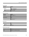
1/4 Clock output
Level ECL 100 K compatible (internally loaded in 50 Ω to -2 V and 47 Ω series terminated)
Period jitter, Typical Measured by TDS694C with options 1M and HD and TDSJIT1.
Refer to Table A-37.
Cycle to cycle jitter, Typical Measured by TDS694C with options 1M and HD and TDSJIT1.
Refer to Table A-38.
Connector Rear panel SMA connector