


Appendix B: Performance Verification (AWG710)
B-98 AWG710&AWG710B Arbitrary Waveform Generator User Manual
1/4 Clock Frequency and 10 MHz Reference Input Tests
These procedures check the 10 MHz reference input function of the AWG710
Arbitrary Waveform Generator.
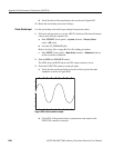
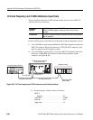
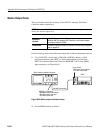
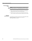
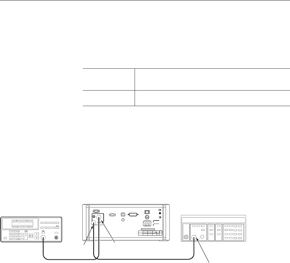
Do the following steps to install the test hookup and set the test equipment controls:
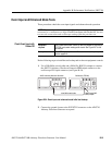
1. Use a 50 Ω SMA coaxial cable and SMA(Fe)–BNC(Ma) adapter to connect the
AWG710 Arbitrary Waveform Generator 1/4 CLOCK OUT connector to the
input A connector on the frequency counter.
2. Use a 50 Ω BNC coaxial cable to connect the AWG710 Arbitrary Waveform
Generator 10 MHz REF IN connector to the function generator output
connector (see Figure B-62).
Figure B-62: 1/4 Clock frequency and 10 MHz reference input initial test hookup
a. Set the frequency counter controls as follows:
Equipment
required
A 50 Ω SMA coaxial cable, A 50 Ω BNC coaxial cable, a
SMA(Fe)–BNC(Ma) adapter, a frequency counter, and a function
generator.
Prerequisites
The AWG710 Arbitrary Waveform Generator must meet the prerequisites
listed on page B-61.
Function Generator (AFG310)
AWG710 Arbitrary Waveform
Generator rear panel
Frequency Counter
50 Ω BNC coaxial cable 50 Ω SMA coaxial cable
10 MHz REF IN
1/4 CLOCK OUT
SMA(Female)-BNC
(Male) adapter
INPUT A
Coupling . . . . . . . . . . . . . . . . . . . . . . . . . . . . AC
FUNCTION . . . . . . . . . . . . . . . . . . . . . . . . . . . . . . A FREQ
Gate time . . . . . . . . . . . . . . . . . . . . . . . . . . . . . . . 0.2 s
Trigger Level . . . . . . . . . . . . . . . . . . . . . . . . . . . . . 0 V