


Appendix B: Performance Verification (AWG710B)
AWG710&AWG710B Arbitrary Waveform Generator User Manual B-31
Pulse Response Tests (Normal Out), (except option 02)
This procedure checks the pulse response characteristics of the AWG710B Arbitrary
Waveform Generator output waveforms at amplitudes of 1 V.
Do the following steps to install the test hookup and set the test equipment controls:
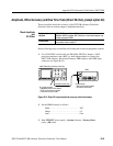
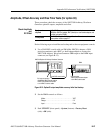
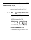
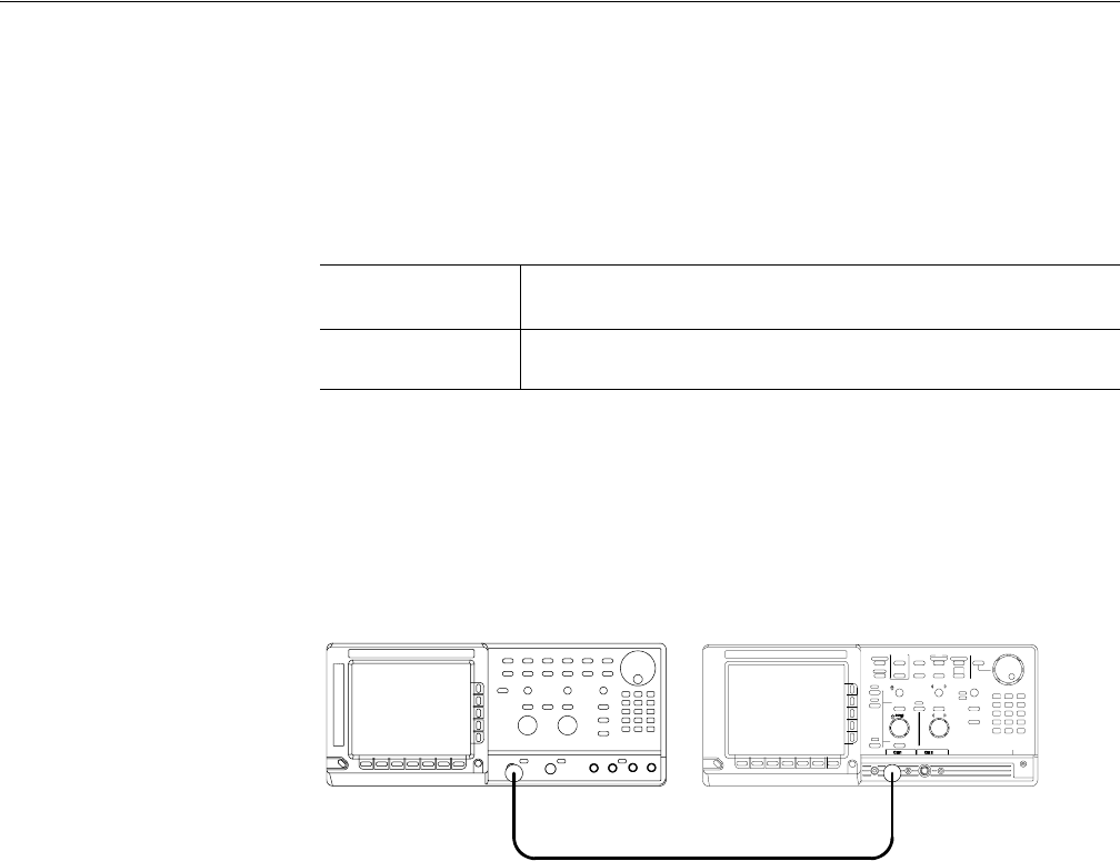
1. Use the 50 Ω SMA coaxial cable to connect the AWG710B Arbitrary
Waveform Generator CH1 output connector to the oscilloscope CH1 input
connector (see Figure B-14).
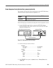
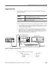
Figure B-14: Pulse response initial test hookup
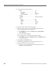
2. Set the oscilloscope controls as follows:
3. Push UTILITY (front–panel)!System (bottom)!Factory Reset (side)
!OK (side).
Equipment
required
A 50 Ω SMA coaxial cable and an oscilloscope (TDS820).
Prerequisites
The AWG710B Arbitrary Waveform Generator must meet the
prerequisites listed on page B-7.
VerticalCH1
CH1 coupling. . . . . . . . . . . . . . . . . . . . . . . . . DC if applicable
CH1 scale . . . . . . . . . . . . . . . . . . . . . . . . . . . 200 mV/div
Horizontal
Sweep . . . . . . . . . . . . . . . . . . . . . . . . . . . . . . 500 ps/div
Trigger
Source. . . . . . . . . . . . . . . . . . . . . . . . . . . . . . CH1
Slope. . . . . . . . . . . . . . . . . . . . . . . . . . . . . . . Positive
Level . . . . . . . . . . . . . . . . . . . . . . . . . . . . . . . 0 V
Mode . . . . . . . . . . . . . . . . . . . . . . . . . . . . . . . Auto
AWG710B Arbitrary Waveform Generator Oscilloscope (TDS820)
50Ω SMA coaxial cable