


Operating Basics
2-6 AWG710&AWG710B Arbitrary Waveform Generator User Manual
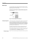
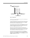
Rear Panel
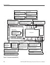
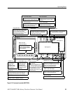
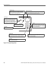
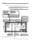
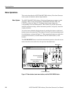
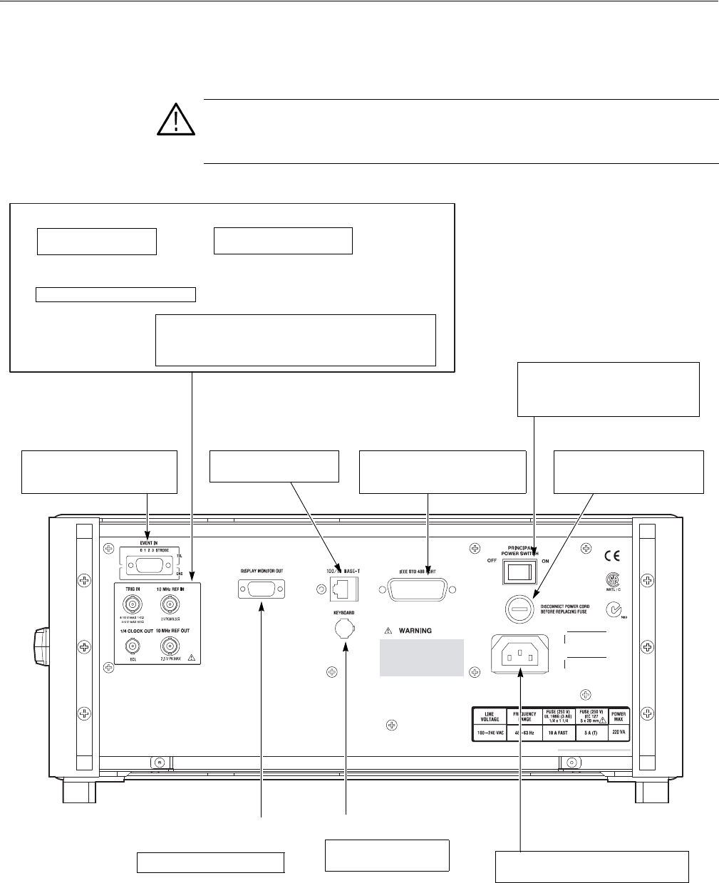
Figure 2-5 and 2-6 show the rear panel signal and power connectors.
Figure 2-5: Rear panel signal and power connectors (AWG710)
CAUTION. To prevent damage to the instrument, only apply signals within the
stipulated range to the INPUT connector.
Do not apply any external voltage to the OUTPUT connector.
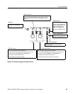
10 MHz REF IN connector
External 10 MHz reference
clock signal input.
TRIG IN connector
External trigger signal
input.
10 MHz REF OUT connector
The internal 10 MHz clock reference signal is output when the
internal clock reference is selected. The external clock reference
signal is output when the external clock reference is selected.
The maximum output level is 1 V
p-p
±0.1V into 50 Ω load
1/4 CLOCK OUT connector
1/4 Sampling clock signal output.
EVENT IN connector
Inputs external event signals. This
signal can be used for sequence
control in Enhanced mode
100/10BASE-T connector
Connect to the Ethernet
network.
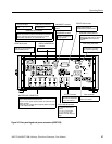
PRINCIPAL POWER SWITCH
Applies power to the standby circuit. In
addition to this switch being on, the front
panel ON/STBY switch must also be
turned on.
IEEE STD 488 connector
A GPIB connector for remote
computer control through an
IEEE 488 standard parallel interface.
Power supply fuse holder
The 10 A fast blow and 5 A (T)
fuse are used for 115 V and
230 V systems, respectively
DISPLAY MONITOR OUT
connector
Connect to an external monitor.
KEYBOARD connector
Connect to a standard PC
101-key keyboard.
Power connector
Connect the provided power cable to this
connector.