


Operating Basics
AWG710&AWG710B Arbitrary Waveform Generator User Manual 2-41
Theory of Operation
This section presents an overview of the AWG710&AWG710B Arbitrary
Waveform Generator hardware, data structures, and operating modes.
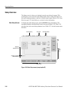
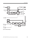
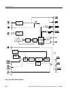
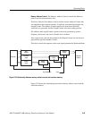
Block Diagram
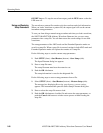
Figure 2-27 and Figure 2-28 show the main hardware blocks that make up the
AWG710& AWG710B Arbitrary Waveform Generator.
CPU. The CPU controls the whole instrument using the GPIB interface, floppy disk
connection, 100/10BASE–T Ethernet connection, user interface through the
display screen and the front–panel, and so forth.
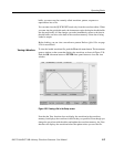
Clock Oscillator. You can select either the internal or external reference clock
source by using the SETUP horizontal menu.
If you select the external source, the reference signal connected to the 10 MHz REF
In connector on the rear panel will be used.
The internal clock is from the reference clock oscillator, which uses direct digital
synthesis (DDS). Figure 2-27 shows the clock oscillator configuration.
Trigger Control. The Trigger Control block controls the Memory Address Control
in the operation mode that you specified from the RUN MODE menu.
Waveform Memory and Shift Register. The Waveform Memory block has 8 bits for
waveform data and 2 bits per channel for markers, thus a total length of 32.4 M
/64.8 M (option 01) (16.2 M /32.4 M (option 01) :AWG710) points. You can set
any value from 960 points to 32.4 M/64.8 M (option 01) (16.2 M /32.4 M (option
01) :AWG710) points for the length of waveform data. It must be in increments of
4.
The Shift Register block is used to provide waveform data from the DAC at a rate
up to 4.2 GS/s (4.0 GS/s : AWG710).
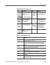
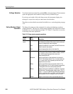
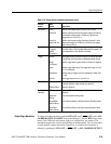
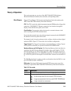
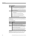
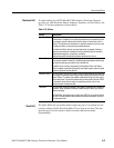
RUN modes. Selecting a RUN mode from the SETUP menu causes one of the
following to operate the AWG710&AWG710B Arbitrary Waveform Generator:
Table 2-13: Run modes
Modes Descriptions
Continuous Consecutively output regardless of existence of a trigger signal.
Triggered The output signal is obtained only once when one of the following is input:
An external trigger signal from the rear panel’s TRIG IN connector.
A trigger signal generated with the front–panel’s FORCE TRIGGER button.
A trigger command from remote device.