


207Setup Relating to Operations From the Control Panel
Chapter 16 Engineering Setup
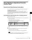
Linking switcher bus and routing switcher destination
To provide links between the switcher bus and routing switcher destination,
make the following settings as required.
Matrix selection: Select the target of link setting from the eight matrices (1 to
8).
Matrix position definition: Set the start address and level for the source and
destination on the S-Bus.
Link table setting: Link a switcher cross-point button and matrix source.
Link bus setting: Link a switcher bus address and routing switcher
destination.
To select a matrix number
Use the following procedure.
1
In the Panel>Config menu, press [External Bus Link].
The External Bus Link menu appears.
The status area shows the current link status.
2
Turn the knobs to select the matrix.
In the status area, the color of the selected part changes.
3
Press [Link Matrix Set].
This confirms the matrix selection and the selected part in the status area
returns to the previous color.
To delete a link
With the link selected, press [Clear].
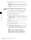
To define the position of a matrix
Specify where in the 1024 × 1024 S-Bus space the link matrix is to be provided,
by setting the source and destination start address.
For the matrix selected in the External Bus Link menu, use the following
procedure.
1
In the Panel>Config>External Bus Link menu, press [Link Matrix Adjust].
The Link Matrix Adjust menu appears.
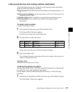
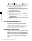
Knob Parameter Adjustment Setting values
1 Link No Link number 1 to 64
2 Link Matrix Matrix number 1 to 8