


257Setup Relating to Switcher Processor
Chapter 16 Engineering Setup
3
In the <Trigger Type> group, select the trigger polarity.
: The trigger causes the relay contacts to be open-circuit or drives
the output high, and holds this state for the specified pulse
width.
: The trigger causes the relay contacts to be shorted or drives the
output low, and holds this state for the specified pulse width.
: Each time the trigger occurs, the relay contacts are alternately
closed or opened, or the output is switched between high and
low.
Status: Depending on the status, the relay contacts are closed or opened,
or the output is switched between high and low.
No Operation: The trigger has no effect on the output.
4
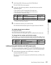
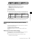
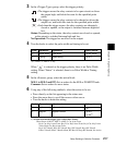
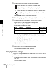
Turn the knobs to select the pulse width and timing to be set.
a) 1: Field 1, 2: Field 2, 3: Any
When “ ” is selected as the trigger polarity, there is no Pulse Width
setting. When “Status” is selected, there is no Pulse Width or Timing
setting.
5
In the <Source> group, select the action block.
M/E-1 to M/E-3 and P/P: Set an action for the M/E or PGM/PST bank.
Common: Set an action for error status.
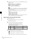
6
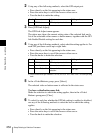
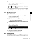
Using any of the following methods, select the action to be set.
• Press directly on the list appearing in the status area.
• Press the arrow keys to scroll the reverse video cursor.
• Turn the knobs to make the setting.
a) • Action list when the trigger type is other than “Status”
When Source is M/E-1, M/E-2, or M/E-3: Cut, Auto Trans
Key1 Cut, Key1 Auto Trans, Key2 Cut, Key2 Auto Trans, Key3 Cut, Key3 Auto
Trans, Key4 Cut, Key4 Auto Trans
Key1 SS ? Recall, Key2 SS ? Recall, Key3 SS ? Recall, Key4 SS ? Recall
Effect ? Recall, Effect ? Recall & Run, KF Run, KF Stop, KF Rewind, No Action
Knob Parameter Adjustment Setting values
3 Pulse Width Pulse width 1 to 60 (fields)
4 Timing Output timing
1 to 3
a)
Knob Parameter Adjustment Setting values
2 Action Action selection
1 to ...
a)
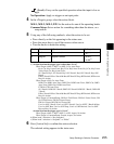
5 Reg No Register number
1 to 4
b)
1 to 99
c)