Chapter 16 Engineering Setup
252
Setup Relating to Switcher Processor
2
Using any of the following methods, select the GPI output port.
• Press directly on the list appearing in the status area.
• Press the arrow keys to scroll the reverse video cursor.
• Turn the knob to make the setting.
3
Press [GPI Link Adjust].
The GPI Link Adjust menu appears.
The status area shows the current setting state of the selected link, and a
list of the selectable video names or button names, together with the GPI
link Enable/Disable setting for each bus.
4
Using any of the following methods, select what the setting applies to. For
each GPI port there can be up to eight links.
• Press directly on the list appearing in the status area.
• Press the arrow keys to scroll the reverse video cursor.
• Turn the knobs to make the selection.
a) These include main pair numbers 1 to 128, and “Cut” and “Auto Trans” on each operating
bank.
5
In the <Video/Button> group, press [Select].
The selected video or button name is reflected in the status area.
To clear a video/button name link
Make the selection to which the setting applies, then in the <Video/
Button> group press [Clear].
6
To select for each bus whether the GPI link setting is enabled or disabled,
use any of the following methods to select the bus to which the setting
applies.
• Press directly on the list appearing in the status area.
• Press the arrow keys to scroll the reverse video cursor.
• Turn the knob to make the selection.
Knob Parameter Adjustment Setting values
1 GPI Port GPI output port selection 1 to 8
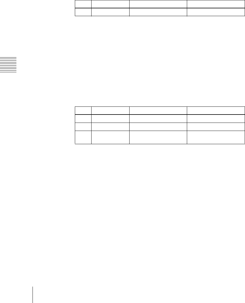
Knob Parameter Adjustment Setting values
1 GPI Port GPI output port selection 1 to 8
2 Link No Link number selection 1 to 8
3 Video/Button No Video or button name
selection
1 to 136
a)


