


Chapter 16 Engineering Setup
280
Setup Relating to Router Interface and Tally
1
In the External Box Assign menu, select [External box1] from the
<Device> group.
2
In the <Matrix Size> group, select [8×1].
3
Turn the knobs to make adjustments.
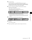
4
In the <Device> group, select [External box2].
5
In the <Matrix Size> group, select [32×1].
6
Turn the knobs to make adjustments.
At this point make the settings of Destination and Level the same as in step
3.
This automatically couples External Box1 and External Box2, forming an
external box with 40 (8+32) inputs.
Tally Group Settings (Group Tally Menu)
With the S-Bus protocol, tally control is possible for groups 1 to 8, but in this
system you can use either groups 1 to 4 or groups 5 to 8.
You can also select whether or not to transfer the tally information over the S-
Bus.
To select the tally groups, use the Router/Tally>Group Tally menu.
To display the Group Tally menu
In the Engineering Setup menu, select VF6 ‘Router/Tally’ and HF2 ‘Group
Tally.’
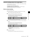
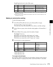
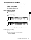
Setting the tally groups
Use the following procedure.
1
In the <Tally Group> group of the Group Tally menu, select the tally
groups.
Group1 to 4: Use groups 1 to 4.
Group5 to 8: Use groups 5 to 8.
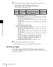
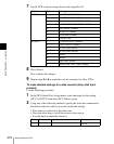
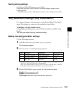
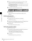
Knob Parameter Adjustment Setting values
1 Source Source start address 1 to 1017
2 Destination Destination start address 1 to 1024
3 Level Level 1 to 8