


251Setup Relating to Switcher Processor
Chapter 16 Engineering Setup
1
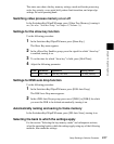
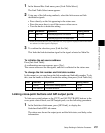
In the Internal Bus Link menu, press [Link Table Select].
The Link Table Select menu appears.
2
Using any of the following methods, select the link source and link
destination signals.
• Press directly on the list appearing in the status area.
• Press the arrow keys to scroll the reverse video cursor.
• Turn the knobs to make the setting.
a) When the selected bus has a key source bus set, a key signal is displayed; when other buses
are selected, a video signal is displayed.
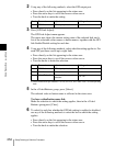
3
To confirm the selection, press [Link Src Set].
This links the link destination signal to the signal selected as Main No.
To initialize the set source address
Press [Init Link Table].
A confirmation message appears; press [Yes].
The source addresses are reassigned, and this is reflected in the status area.
To change the link number and link table number
In this menu too, you can change the link number and link table number. To do
this, turn the knobs as follows to make the setting, then press [Link Table Set].
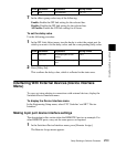
Linking cross-point buttons and GPI output ports
To link cross-point buttons or the [CUT] and [AUTO TRANS] buttons in the
cross-point control block, and GPI output ports, use the following procedure.
1
In the Switcher>Link menu, press [GPI Link], to display the
Switcher>Link>GPI Link menu.
The status area shows the output ports and the link status, and delay value
information.
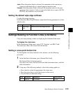
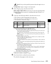
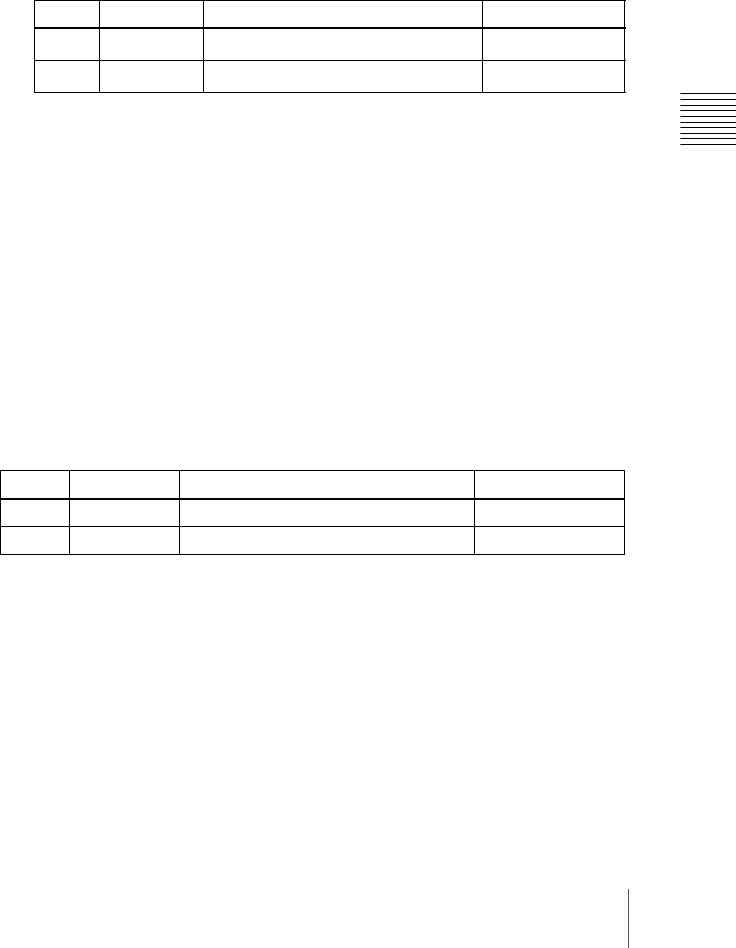
Knob Parameter Adjustment Setting values
4 Main No
Video/key signal for link source
a)
1 to 128
5No
Video/key signal for link destination
a)
1 to 128
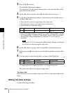
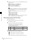
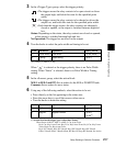
Knob Parameter Adjustment Setting values
1 Link No Link to which setting applies 1 to 64
3 Link Table No Link table selection 1 to 8