


Chapter 16 Engineering Setup
278
Setup Relating to Router Interface and Tally
Setup Relating to Router Interface and Tally
Router Interface Settings (Router Menu)
In this system, the interface with a router (routing switcher) uses the S-Bus
protocol. It is therefore necessary to assign inputs and outputs of the switcher
and so on to an S-Bus space.
To carry out this assignment, use the Router/Tally>Router menu. The
assignment is common to the parallel and serial tallies.
To display the Router menu
In the Engineering Setup menu, select VF6 ‘Router/Tally’ and HF1 ‘Router.’
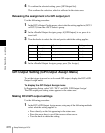
The status area shows the device names to be assigned to the S-Bus space, the
matrix size, source address, destination address, and level.
Assigning switcher inputs and outputs to S-Bus space
Use the following procedure.
1
In the <Device> group of the Router/Tally>Router menu, select the device
to which the settings apply.
SWR1: Settings apply to switcher 1.
SWR2: Settings apply to switcher 2.
Note
When there are two switchers on the same network, the SWR2 (second
switcher) settings are required. If there is only one switcher, the settings
are not required.
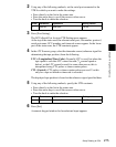
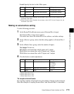
2
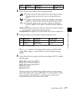
In the <Matrix Size> group, select the matrix size.
Standard (136 × 138): Assign the switcher S-Bus space at full size. You
can assign all switcher inputs and outputs to the S-Bus space, but this
causes some waste of S-Bus space.
Compact (128 × 128): Assign the switcher S-Bus space at compact size.
It is not possible to assign all switcher inputs and outputs to the S-Bus
space, but the S-Bus space can be used efficiently.
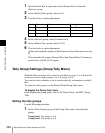
3
Turn the knobs to set the parameters for the following items.
Source: Specify the start address of the matrix source.
Destination: Specify the start address of the matrix destination.