


271Setup Relating to DCU
Chapter 16 Engineering Setup
2
In the <Trigger Type> group, select the trigger polarity.
: The trigger causes the relay contacts to be open-circuit or drives
the output high, and holds this state for the specified pulse
width.
: The trigger causes the relay contacts to be shorted or drives the
output low, and holds this state for the specified pulse width.
: Each time the trigger occurs, the relay contacts are alternately
closed or opened, or the output is switched between high and
low.
Status: Depending on the status, the relay contacts are closed or opened,
or the output is switched between high and low.
No Operation: The trigger has no effect on the relay state or output level.
3
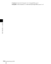
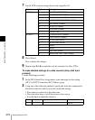
Turning the knobs, select the pulse width and timing to be set.
a) 1: Field 1, 2: Field 2, 3: Any
When “ ” is selected as the trigger polarity, there is no Pulse Width
setting. When “Status” is selected, there is no Pulse Width or Timing
setting.
4
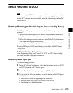
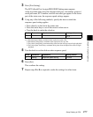
In the <Source Device> group, select the control panel or DCU to handle
the GPI output.
SCU1: ID1 control panel (PNL1)
SCU2: ID2 control panel (PNL2)
SCU3: ID3 control panel (PNL3)
DCU1: ID1 DCU
DCU2: ID2 DCU
When the action set in the following step 5 is carried out on the control
panel selected here, this causes a GPI output. It is also possible to output
error information. When the DCU is selected, you can output error
information by means of the action set in step 5.
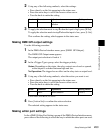
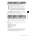
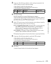
Knob Parameter Adjustment Setting values
1 No GPI output 1 to 50
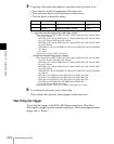
Knob Parameter Adjustment Setting values
3 Pulse Width Pulse width 1 to 60 (fields)
4 Timing Output timing
1 to 3
a)