


American Steel Design
Section 2
2-14
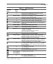
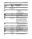
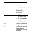
Table 2.1 - AISC Parameters
Parameter Default Description
Name Value
STIFF Member length or depth
of beam whichever is
greater
Spacing of stiffeners for plate girder design
TRACK 0.0
Controls the level of detail to which results
are reported.
0 = Minimum detail
1 = Intermediate detail level
2 = Maximum detail (see Figure2.1)
DMAX 1000 in. Maximum allowable depth.
DMIN 0.0 in. Minimum allowable depth.
RATIO 1.0 Permissible ratio of the actual to allowable
stresses.
WELD 1 for closed sections
2 for open sections
Weld type, as explained in section 2.12. A
value of 1 will mean welding is on one side
only except for wide-flange or tee sections,
where the web is always assumed to be
welded on both sides. A value of 2 will mean
welding on both sides. For closed sections
like pipe or tube, the welding will be on one
side only.
BEAM 1.0 0.0 = design at ends and those locations
specified by the SECTION command.
1.0 = design at ends and at every 1/12
th
point
along member length. (Default)
PROFILE None Used in member selection. See section
5.47.1 for details.
WMIN See Sect. 2.12 Minimum welding thickness.
WMAX See Sect. 2.12 Maximum welding thickness.
WSTR 0.4 x FYLD Allowable welding stress.
DFF None
(Mandatory for deflection
check)
"Deflection Length" / Maxm. allowable local
deflection
DJ1 Start Joint
of member
Joint No. denoting starting point for
calculation of "Deflection Length" (See Note
1)