American Steel Design
Section 2
2-84
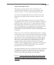
The design method is the allowable stress method, using mainly
the rules stated in the AISC ASD 9
th
edition code. Only code
checking is currently available for castellated beams. Member
selection is not.
Design parameters:
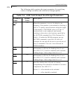
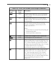
The following table contains a list of parameters and their default
values.
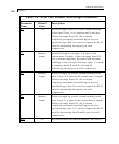
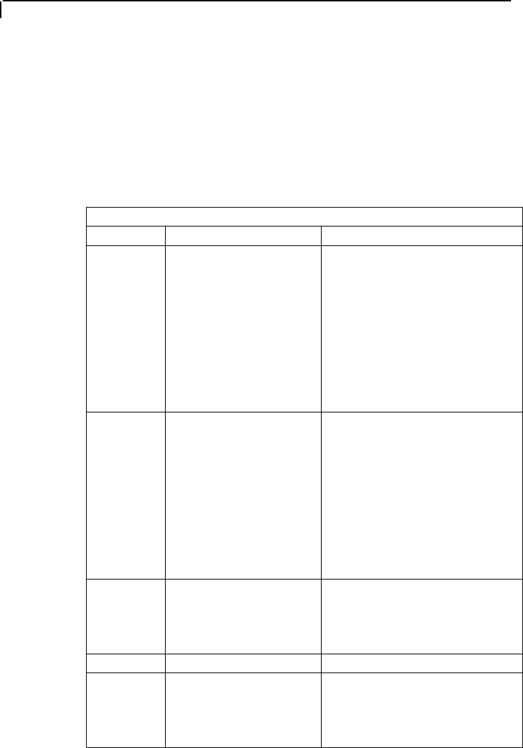
Table 2.7
Parameter Default Value Description
SOPEN 1.5e + b is the minimum
allowable value. Any
user-specified value
higher than or equal to
this minimum will be
used by the program.
“e” and “b” are as
described in the next
figure.
Distance from the start of the
member to the center of the first
hole.
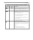
EOPEN 1.5e + b is the minimum
allowable value. Any
user-specified value
higher than or equal to
this minimum will be
used by the program.
“e” and “b” are as
described in the next
figure.
Distance from the center of the
last hole to the end of the
member.
UNL Member length Unsupported length of
compression flange for
calculating allowable bending
stress.
FYLD 36 ksi Yield Stress of Steel
CB 1.0 Cb value used for computing
the allowable bending stress per
Chapter F of AISC
specifications.


