


Section 2
2-15
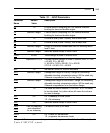
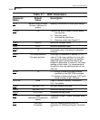
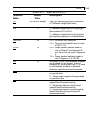
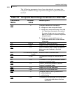
Table 2.1 - AISC Parameters
Parameter Default Description
Name Value
DJ2
End Joint of member Joint No. denoting end point for calculation
of "Deflection Length" (See Note 1)
CAN 0 0 = deflection check based on the principle
that maximum deflection occurs within the
span between DJ1 and DJ2.
1 = deflection check based on the principle
that maximum deflection is of the cantilever
type (see note below)
TORSION 0.0 0.0 = No torsion check performed.
1.0 = Perform torsion check based on rules
of AISC T114.
TAPER 1.0 0.0 = Design tapered I-section based on
rules of Chapter F and Appendix B
only. Do not use the rules of Appendix
F.
1.0 = Design tapered I-sections based on
rules of Appendix F of AISC-89.
OVR 1.0 Overstress Factor. All the allowable stresses
are multiplied by this number. It may be
assigned any value greater than 0.0. Is used
to communicate increases in allowable
stress for loads like wind and earthquake.
AXIS 1 1 - Design single angles for bending based
on principal axis.
2 - Design single angles for bending based
on geometric axis.
FLX 1 1 – Single Angle Member is not fully braced
against lateral torsional buckling.
2 - Single Angle Member is fully braced
against lateral torsional buckling.
3 - Single Angle Member is braced against
lateral torsional buckling at the point of
maximum moment.