American Concrete Design
Section 3
3-32
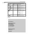
There are two categories of output for bending moments
(envelopes are reported) and flexural reinforcing in the Slab
Design Report window.
a. Moment Diagram page allows to browse the results
displayed for each of the transverse sections of the strip or
user defined section. The force shown is as previously
calculated (maximum or average) and the reported required
reinforcing is based on that force.
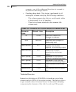
b. Design Report page displays governing values of bending
moments, as well as top and bottom reinforcing within a
strip or along a user defined section. If the Design for
Maximum Moments option was chosen, the program reports
the maximum values of positive and negative moments. If
the Design for Average Moments option was selected, the
program calculates the average negative moment and the
average positive moment for the strip or user’s section.
Those values are reported as the Design Moment (rows
labeled Top and Bottom) and are used by the program for
computation of reinforcing areas.
Flexural design notes:
As the program obtains values of internal forces from finite
element analysis, the design process is not constrained by the
limitations of traditional methods such as Direct Design and
Equivalent Frame, Section 13.5 of ACI 318-02. However, the
provisions of 13.5.3 for unbalanced moment transfer have been
implemented.
Reinforcement calculations for slab panels are based on Chapter 10
of ACI 318-02. The reinforcement areas are computed for a
notional band one unit of length wide.
The minimum reinforcing ratio complies with the limits prescribed
for shrinkage and temperature reinforcement in Section 7.12. The
maximum reinforcing ratio corresponds to the net tensile strain at
nominal strength equal to 0.004 (Clause 10.3.5).


