STAAD Commands and Input Instructions
Section 5
5-236
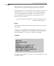
then it defaults to 1.0 for those joints; in which case the entire
influence area associated with the joint(s) will be considered.
For load generation on a closed type structure defined as a PLANE
FRAME, influence area for each joint is calculated considering
unit width perpendicular to the plane of the structure. The user
can accommodate the actual width by incorporating it in the
Exposure Factor as follows.
Exposure Factor (User Specified) = (Fraction of influence area) X
(influence width for joint)
Notes
All intensities, heights and ranges must be provided in the current
unit system.
If necessary, the INTENSITY, EXPOSURE, command lines can be
continued on to additional lines by ending all but last line with a
space and hyphen (-). Use up to 11 lines for a command.
Example
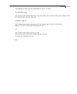
UNIT FEET
DEFINE WIND LOAD
TYPE 1
INTENSITY 0.1 0.15 HEIGHT 12 24
EXPOSURE 0.90 YRANGE 11 13
EXPOSURE 0.85 JOINT 17 20 22
LOAD 1 WIND LOAD IN X-DIRECTION
WIND LOAD X 1.2 TYPE 1
For additional examples, see section 5.32.12 and example 15 in the
Examples manual.


