


Section 5
5-235
e
1
,e
2
,e
3
...e
m
exposure factors. A value of 1.0 means that the
wind force may be applied on the full influence area
associated with the joint(s) if they are also exposed
to the wind load direction. Limit: 99 factors.
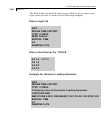
joint-list Joint list associated with Exposure Factor (joint
numbers or “TO” or “BY”) or enter only a group
name.
f
1
and f
2
global coordinate values to specify Y (or Z if Z UP)
vertical range for Exposure Factor.
If the command EXPOSURE is not specified or if a joint is not
listed in an Exposure, the exposure factor for those joints is chosen
as 1.0.
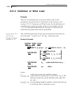
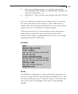
Description
All loads and heights are in current unit system. In the list of
intensities, the first value of intensity acts from the ground level
up to the first height. The second intensity (p
2
) acts in the Global
vertical direction between the first two heights (h
1
and h
2
) and so
on. The program assumes that the ground level has the lowest
global vertical coordinate of any joint entered for the structure.
Only exposed surfaces bounded by members (not by plates or
solids) will be used. The joint influence areas are computed based
on surface member selection data entered in section 5.32.12 and
based on the wind direction for a load case. Only joints actually
exposed to the wind and connected to members will be loaded.
The individual bounded areas must be planar surfaces, to a close
tolerance, or they will not be loaded.
See Section
1.17.3 and
5.32.12
Exposure factor (e) is the fraction of the influence area associated
with the joint(s) on which the load may act if it is also exposed to
the wind load. Total load on a particular joint is calculated as
follows.
Joint load = (Exposure Factor) X (Influence Area) X (Wind Intensity)
The exposure factor may be specified by a joint-list or by giving a
vertical range within which all joints will have the same exposure.
If an exposure factor is not entered or not specified for a joint,