American Concrete Design
Section 3
3-30
compute - one of the orthogonal directions is assumed to
be parallel to the design section.
c. Punching shear check. This design is performed for all
rectangular columns satisfying the following conditions:
- The column supports the slab at a node located within
a design panel or on its boundary,
- There are no beams attached to the common slab-
column node.
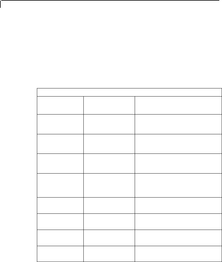
Table 3.6 - INTERACTIVE SLAB DESIGN PARAMETERS
Parameter
Name
Default Value Description
Fc 4.0 ksi
specified compressive
strength of concrete
Fyld 60.0 ksi
specified yield strength of
reinforcing steel
Min. bar size # 3
smallest size of rebar
required in reinforcing output
Max. bar size # 8 largest size of rebar
permitted in reinforcing
output
Min. spacing 4.0 in minimum c/c bar spacing
allowed in reinforcing output
Max. spacing 8.0 in maximum c/c bar spacing
allowed in reinforcing output
Top cover 1.5 in clear concrete cover for top
bars
Bottom cover 1.5 in clear concrete cover for bottom
bars
Technical Overview
Interactive slab design in STAAD.Pro is based on a prior finite
element analysis (FEA) of the entire structure. The analysis allows
to get accurate values of internal forces for the model, including
component plate elements of the slab. As with any FEA project,


