


Section 1
1-35
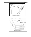
Output of Solid Element Stresses
Element stresses may be obtained at the center and at the joints of
the solid element. The items that are printed are :
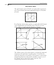
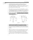
Normal Stresses : SXX, SYY and SZZ
Shear Stresses : SXY, SYZ and SZX
Principal stresses : S1, S2 and S3.
Von Mises stresses: __________________________
SIGE= .707 √ (S1-S2)
2
+ (S2-S3)
2
+ (S3-S1)
2
Direction cosines : 6 direction cosines are printed, following the
expression DC, corresponding to the first two principal stress
directions.
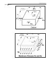
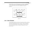
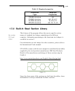
1.6.3 Surface Element
For any panel type of structural component, modeling requires
breaking it down into a series of plate elements for analysis
purposes. This is what is known in stress analysis parlance as
meshing. When a user chooses to model the panel component using
plate elements, he/she is taking on the responsibility of meshing.
Thus, what the program sees is a series of elements. It is the user's
responsibility to ensure that meshing is done properly. Examples
of these are available in example problems 9, 10, 23, 27, etc. (of
the Examples manual) where individual plate elements are
specified.
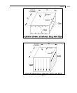
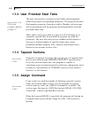
With the new Surface type of entity, the burden of meshing is
shifted from the user to the program to some degree. The entire
wall or slab is hence represented by just a few "Surface" entities,
instead of hundreds of elements. When the program goes through
the analysis phase, it will subdivide the surface into elements by
itself. The user does not have to instruct the program in what
manner to carry out the meshing.