STAAD Commands and Input Instructions
Section 5
5-24
5.11 Joint Coordinates Specification
Purpose
These commands allow the user to specify and generate the
coordinates of the JOINTs of the structure. The JOINT
COORDINATES command initiates the specification of the
coordinates. The REPEAT and REPEAT ALL commands allow
easy generation of coordinates using repetitive patterns.
General format:
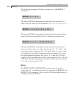
JOINT COORDINATES (CYLINDRICAL (REVERSE)) (NOCHECK) band-spec
i
1
, x
1
, y
1
, z
1
, ( i
2
, x
2
, y
2
, z
2
, i
3
)
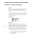
REPEAT n, xi
1
, yi
1
, zi
1
, (xi
2
, yi
2
, zi
2
,..., xi
n
, yi
n
, zi
n
)
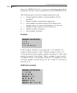
REPEAT ALL n, xi
1
, yi
1
, zi
1
, (xi
2
, yi
2
, zi
2
,..., xi
n
, yi
n
, zi
n
)
n is limited to 150
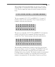
JTORIG xOrigin yOrigin zOrigin
band-spec = (
NOREDUCE BAND)
NOCHECK= Do not perform check for multiple structures or
orphan joints.
Description
The command JOINT COORDINATES specifies a Cartesian
Coordinate System (see Figure 1.2). Joints are defined using the
global X, Y and Z coordinates. The command JOINT
COORDINATES CYLINDRICAL specifies a Cylindrical
Coordinate System (see Figure 1.3). Joints are defined using the r,
θ and z coordinates. JOINT COORDINATES CYLINDRICAL
REVERSE specifies a Reverse Cylindrical Coordinate system (see
Figure 1.4). Joints are defined using the r, y and θ coordinates.
See Section
1.5.1


