


American Steel Design
Section 2
2-16
NOTES:
1) When performing the deflection check, the user can choose
between two methods. The first method, defined by a value 0
for the CAN parameter, is based on the local displacement.
Local displacement is described in section 5.43 of this manual.
If the CAN parameter is set to 1, the check will be based on
cantilever style deflection. Let (DX1, DY1,DZ1) represent the
nodal displacements (in global axes) at the node defined by
DJ1 (or in the absence of DJ1, the start node of the member).
Similarly, (DX2, DY2,DZ2) represent the deflection values at
DJ2 or the end node of the member.
Compute Delta = SQRT((DX2-DX1)**2 + (DY2-DY1)**2 +
(DZ2-DZ1)**2)
Compute Length = distance between DJ1 & DJ2 or, between
start node and end node, as the case may be.
Then, if CAN is specified a value 1, dff = L/Delta
Ratio due to deflection = DFF/dff
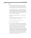
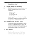
2) If CAN = 0, deflection length is defined as the length that is
used for calculation of local deflections within a member. It
may be noted that for most cases the “Deflection Length” will
be equal to the length of the member. However, in some
situations, the “Deflection Length” may be different. For
example, refer to the figure below where a beam has been
modeled using four joints and three members. The “Deflection
Length” for all three members will be equal to the total length
of the beam in this case. The parameters DJ1 and DJ2 should
be used to model this situation. Also the straight line joining
DJ1 and DJ2 is used as the reference line from which local
deflections are measured. Thus, for all three members here,
DJ1 should be "1" and DJ2 should be "4".