


American Concrete Design
Section 3
3-26
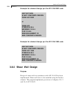
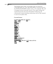
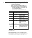
Notes regarding the above example:
1. Command SET DIVISION 12 indicates that the surface boundary
node-to-node segments will be subdivided into 12 fragments prior
to finite element mesh generation.
2. Four surfaces are defined by the SURFACE INCIDENCES
command.
3. The SUPPORTS command includes the support generation
feature. For instance, the line 2 TO 5 GEN PIN assigns pinned
supports to all nodes between nodes 2 and 5. As the node-to-node
distances were previously subdivided by the SET DIVISION 12
command, there will be an additional 11 nodes between nodes 2
and 5. As a result, all 13 nodes will be assigned pinned supports.
Please note that the additional 11 nodes are not individually
accessible to the user. They are created by the program to enable
the finite element mesh generation and to allow application of
boundary constraints.
4. Surface thickness and material constants are specified by the
SURFACE PROPERTY and SURFACE CONSTANTS,
respectively.
5. The shear wall design commands are listed between lines START
SHEARWALL DES and END. The CODE command selects the
design code that will be the basis for the design. The DESIGN
SHEARWALL LIST command is followed by a list of previously
defined Surface elements intended as shear walls and/or shear wall
components. Refer to the beginning of this section for references
to all related commands.
Technical Overview
The program implements provisions of Chapter 14 of ACI-318-02
and relevant provisions from Chapters 10 and 11, as referenced
therein, for all active load cases. The wall is designed as an
unbraced reinforced wall. The following steps are performed for
each of the horizontal sections of the wall set using the SURFACE
DIVISION command whose default value is 10.