


American Steel Design
Section 2
2-28
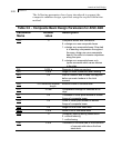
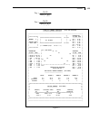
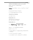
Vertical stress,
Fv
VY
AX
CV MX
JW
=+
×
Direct stress,
Fd
FX
AX
MZ
SZ
MY
SY
=+ +
**
* The moments MY and MZ are taken as absolute values, which may result
in some conservative results for asymmetrical sections like angle, tee and
channel.
Combined force
FFF
comb h v d
=
22
+ + F
2
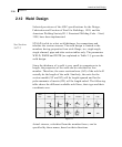
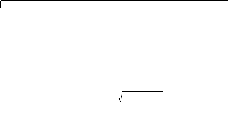
Weld thickness
=
F
F
comb
w
where F
w
= Allowable weld stress, default value is 0.4 FYLD
(Table 2.1).
The thickness t is rounded up to the nearest 1/16th of an inch and
all the stresses are recalculated. The tabulated output prints the
latter stresses. If the parameter TRACK is set to 1.0, the output
will include the weld properties. The program does not calculate
the minimum weld thickness as needed by some codes, but checks
only against the minimum thickness as provided by the user (or
1/16th inch if not provided).
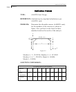
When the TRUSS qualifier is used with SELECT WELD
command, the program will design the welds required for truss
angle and double angle members that are attached to gusset plates.
The program reports the number of welds (two for single angles,
four for double angles), and the length required for each weld. The
thickness of the weld is taken as 1/4 inch (6 mm) for members up
to 1/4 inch (6 mm) thick, and 1/16 inch (1.5 mm) less than the
angle thickness for members greater than 1/4 inch (6 mm) thick.
Minimum weld length is taken as four times weld thickness.