Section 5
5-383
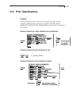
d1, d2 - coordinates in the direction orthogonal to
ξ, delineating a fragment of the full cross-
section for which the output is desired.
s1, ...,si - list of surfaces for output generation
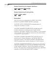
Note: If the keyword ALONG is omitted, direction Y
(default) is assumed.
If command AT is omitted, output is provided for
all sections along the specified (or default) edge.
Number of sections will be determined from the
SURFACE DIVISION X or SURFACE DIVISION
Y input values.
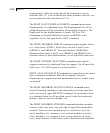
If the BETWEEN keyword is omitted, the output is
generated based on full cross-section width.
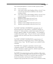
The attributes associated with surfaces, and the sections of this
manual where the information may be obtained, are listed below:
Attributes Related
Sections
Surfaces incidences - 5.13.3
Openings in surfaces - 5.13.3
Local coordinate system for surfaces - 1.6.3
Specifying sections for stress/force output - 5.13.3
Property for surfaces - 5.21.2
Material constants - 5.26.3
Surface loading - 5.32.3.4
Stress/Force output printing - 5.42
Shear Wall Design - 3.8.2, 5.53


