


Section 2
2-61
2.14.7 Flexural Design Strength
In LRFD, the flexural design strength of a member is determined
by the limit state of lateral torsional buckling. Inelastic bending is
allowed and the basic measure of flexural capacity is the plastic
moment capacity of the section. The flexural resistance is a
function of plastic moment capacity, actual laterally unbraced
length, limiting laterally unbraced length, buckling moment and
the bending coefficient. The limiting laterally unbraced length L
r
and buckling moment M
r
are functions of the section geometry and
are calculated as per the procedure of Chapter F. The purpose of
bending coefficient C
b
is to account for the influence of the
moment gradient on lateral-torsional buckling. This coefficient can
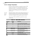
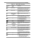
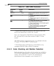
be specified by the user through the use of parameter CB (see
Table 2.2) or may be calculated by the program (if CB is specified
as 0.0). In the absence of the parameter CB, a default value of 1.0
will be used. The procedure for calculation of design strength for
flexure also accounts for the presence of residual stresses of
rolling. To specify laterally unsupported length, the parameters
UNT/UNB (see Table 2.2) can be used.
2.14.8 Combined Axial Force And Bending
The interaction of flexure and axial forces in singly and doubly
symmetric shapes is governed by formulas H1-1a and H1-1b.
These interaction formulas cover the general case of biaxial
bending combined with axial force. They are also valid for
uniaxial bending and axial force.
2.14.9 Design for Shear
The procedure of Sect. F2 of the LRFD Specification is used in
STAAD to design for shear forces in members. Shear strength as
calculated in LRFD is governed by the following limit states: Eq.
F2-1a by yielding of the web; Eq. F2-2a by inelastic buckling of
the web; Eq. F2-3a by elastic buckling of the web. Shear in wide
flanges and channel sections is resisted by the area of the web,
which is taken as the overall depth times the web thickness.