


General Description
Section 1
1-4
1.5 Structure Geometry and Coordinate Systems
A structure is an assembly of individual components such as
beams, columns, slabs, plates etc.. In STAAD, frame elements and
plate elements may be used to model the structural components.
Typically, modeling of the structure geometry consists of two
steps:
A. Identification and description of joints or nodes.
B. Modeling of members or elements through specification of
connectivity (incidences) between joints.
In general, the term MEMBER will be used to refer to frame
elements and the term ELEMENT will be used to refer to
plate/shell and solid elements. Connectivity for MEMBERs may be
provided through the MEMBER INCIDENCE command while
connectivity for ELEMENTs may be provided through the
ELEMENT INCIDENCE command.
F
or input,
see sections
5.11 to 5.17
STAAD uses two types of coordinate systems to define the
structure geometry and loading patterns. The GLOBAL coordinate
system is an arbitrary coordinate system in space which is utilized
to specify the overall geometry & loading pattern of the structure.
A LOCAL coordinate system is associated with each member (or
element) and is utilized in MEMBER END FORCE output or local
load specification.
1.5.1 Global Coordinate System
The following coordinate systems are available for specification of
the structure geometry.
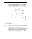
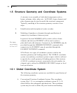
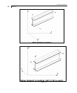
A. Conventional Cartesian Coordinate System: This coordinate
system (Fig. 1.2) is a rectangular coordinate system (X, Y, Z)
which follows the orthogonal right hand rule. This coordinate
system may be used to define the joint locations and loading