Section 2
2-23
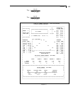
UNIT INCH
PARAMETER
CODE AISC
BEAM 1 ALL
TRACK 2 ALL
DR1 0.3135 ALL
WID 69.525 ALL
FPC 3.0 ALL
THK 4.0 ALL
CMP 1 ALL
CHECK CODE ALL
SELECT ALL
2.10 Plate Girders
Plate girders may be designed according to Chapter G of the AISC
specifications. The generalized ISECTION specification capability
available in the User Table facility may be used to specify the
plate girder sections. The AISC welded plate girder shapes(pages
2-230 and 2-231 - AISC 9th Edition) are available in the Steel
Section library of the program. Both CODE CHECKING &
MEMBER SELECTION may be performed when sections are
specified from a standard AISC plate girder section table or
through the generalized ISECTION facility. Parameter STIFF (see
Table 2.1) may be used to specify stiffener spacing so that the
right allowable shear stress may be calculated. The program
automatically calculates the flange stresses according to the
requirements of section G2.
2.11 Tabulated Results of Steel Design
For code checking or member selection, the program produces the
results in a tabulated fashion. The items in the output table are
explained as follows:


