Section 5
5-271
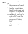
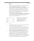
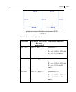
Illustration of Notes Item (6) for FLOOR LOAD
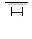
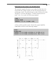
The attached example illustrates a case where the floor has to be
sub-divided into smaller regions for the floor load generation to
yield proper results. The internal angle at node 6 between the sides
108 and 111 exceeds 180 degrees. A similar situation exists at
node 7 also. As a result, the following command
LOAD 1
FLOOR LOAD
YRANGE 11.9 12.1 FLOAD –0.35
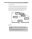
will not yield acceptable results. Instead, the region should be
subdivided as shown in the following example
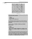
LOAD 1
FLOOR LOAD
YRANGE 11.9 12.1 FLOAD –0.35 XRA –0.1 15.1 ZRA –0.1 8.1
YRANGE 11.9 12.1 FLOAD –0.35 XRA 4.9 10.1 ZRA 7.9 16.1
Figure 5.29


