Section 1
1-87
A Harmonic loading is one in which can be described using the
following equation
)t ( sinF)t( F
0
φ+ω
=
In the above equation,
F(t) = Value of the forcing function at any instant of time "t"
F
0
= Peak value of the forcing function
ω
= Frequency of the forcing function
φ = Phase Angle
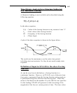
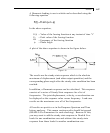
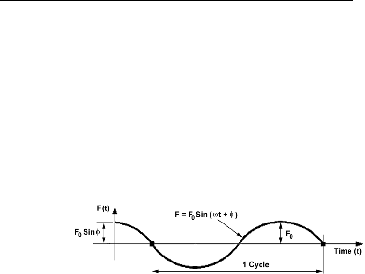
A plot of the above equation is shown in the figure below.
Figure 1.38
The results are the steady-state response which is the absolute
maximum of displacement (and other output quantities) and the
corresponding phase angle after the steady state condition has been
reached.
In addition, a Harmonic response can be calculated. This response
consists of a series of Steady State responses for a list of
frequencies. The joint displacement, velocity, or acceleration can
be displayed as the response value versus frequency. Load case
results are the maximums over all of the frequencies.
All results are positive as in the Response Spectrum and Time
history analyses. This means section results should be ignored
(BEAM 0.0 in Parameters for code checking). Because of this,
you may want to add the steady state response to Dead & Live
loads for one combination case and subtract the steady state
response from those loads for another combination case.


