


American Concrete Design
Section 3
3-8
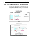
3.6.2 Design for Shear
Shear reinforcement is calculated to resist both shear forces and
torsional moments. Shear forces are calculated at a distance
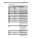
(d+SFACE) and (d+EFACE) away from the end nodes of the beam.
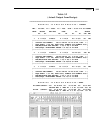
SFACE and EFACE have default values of zero unless provided
under parameters (see Table 3.1). The value of the effective depth
"d" used for this purpose accounts for the actual center of gravity
of the main reinforcement calculated under flexural design. The
relevant clauses of ACI 318 are used to calculate the reinforcement
for shear forces and torsional moments. Based on the total stirrup
reinforcement required, the size of bars, the spacing, the number of
bars and the distance over which they are provided are calculated.
Stirrups are always assumed to be 2-legged.
3.6.3 Design for Anchorage
In the output for flexural design, the anchorage details are also
provided. At any particular level, the START and END coordinates
of the layout of the main reinforcement is described along with the
information whether anchorage in the form of a hook or
continuation is required or not at these START and END points.
The coordinates of these START and END points are obtained
after taking into account the anchorage requirements. Anchorage
length is calculated on the basis of the Clauses described in
Chapter 12 of ACI 318.